EasyManua.ls Logo

miniDSP Flex - Signal Flow Diagram

miniDSP Flex
86 pages
Print Icon
To Next Page IconTo Next Page
To Previous Page IconTo Previous Page
Loading...
3/15/23, 9:45 AM
Print or save - miniDSP Flex
https://docs.minidsp.com/product-manuals/flex/print_page.html
Signal ow
The diagram below is a simplied representation of the signal ow through the miniDSPFlex (without DiracLive):
OUTPUT CHANNELS
ROUTING
INPUT
CHANNELS
Routing matrix
2x4
INPUTS
OUT #1
OUT #2
OUT #3
OUT #4
PEQ
PEQ
5-way
stereo
selector
switch
USB
TOSLINK
SPDIF
Analog/
Option
Bluetooth
miniDSP Device ConsoleConfigured by:
PEQ
Xover
FIR
Gain
PEQ
Xover
FIR
Gain
PEQ
Xover
FIR
Gain
PEQ
Xover
FIR
Gain
Gain
Gain
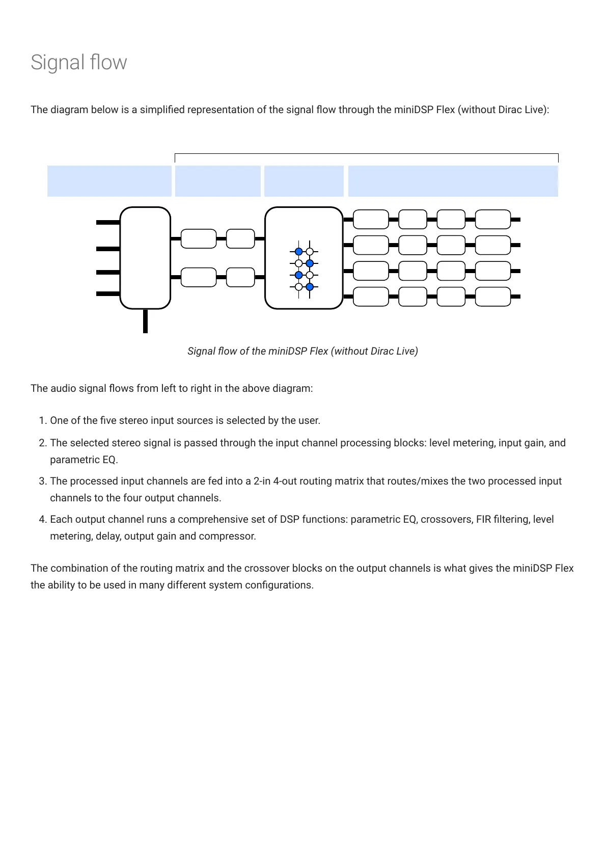
Signal ow of the miniDSPFlex (without DiracLive)
The audio signal ows from left to right in the above diagram:
1. One of the ve stereo input sources is selected by the user.
2. The selected stereo signal is passed through the input channel processing blocks: level metering, input gain, and
parametric EQ.
3. The processed input channels are fed into a 2-in 4-out routing matrix that routes/mixes the two processed input
channels to the four output channels.
4. Each output channel runs a comprehensive set of DSP functions: parametric EQ, crossovers, FIR ltering, level
metering, delay, output gain and compressor.
The combination of the routing matrix and the crossover blocks on the output channels is what gives the miniDSPFlex
the ability to be used in many different system congurations.

Other manuals for miniDSP Flex

Related product manuals