Print or save - miniDSP Flex
https://docs.minidsp.com/product-manuals/flex/print_page.html
Input channels 1 and 2 are
mixed to output channel 1
at 0 dB (no attenuation)
0 DB
INPUT 2
Output 1
0 DB
INPUT 1
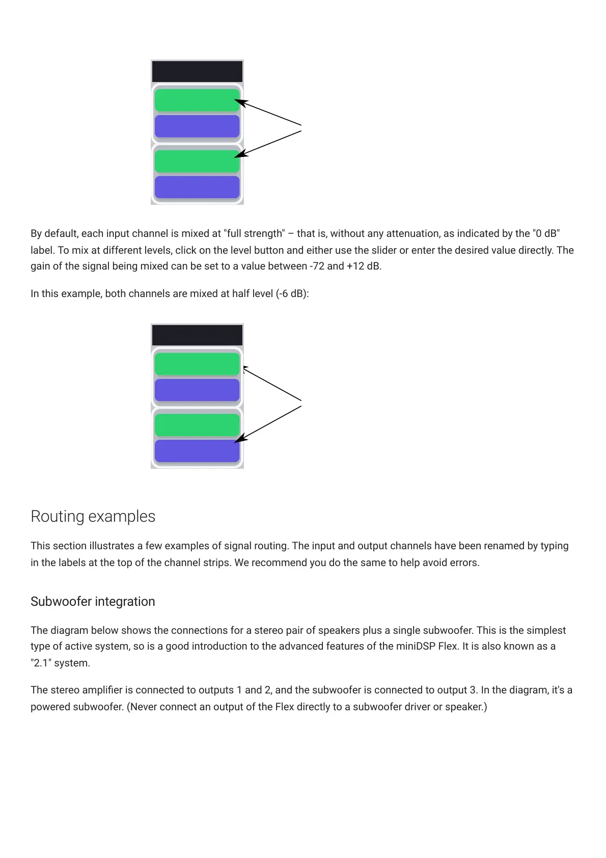
By default, each input channel is mixed at "full strength" – that is, without any attenuation, as indicated by the "0 dB"
label. To mix at different levels, click on the level button and either use the slider or enter the desired value directly. The
gain of the signal being mixed can be set to a value between -72 and +12 dB.
In this example, both channels are mixed at half level (-6 dB):
-6 DB
INPUT 2
Input channels 1 and 2 are
mixed to output channel 1
at -6 dB dB
Output 1
-6 DB
INPUT 1
Routing examples
This section illustrates a few examples of signal routing. The input and output channels have been renamed by typing
in the labels at the top of the channel strips. We recommend you do the same to help avoid errors.
Subwoofer integration
The diagram below shows the connections for a stereo pair of speakers plus a single subwoofer. This is the simplest
type of active system, so is a good introduction to the advanced features of the miniDSPFlex. It is also known as a
"2.1" system.
The stereo amplier is connected to outputs 1 and 2, and the subwoofer is connected to output 3. In the diagram, it's a
powered subwoofer. (Never connect an output of the Flex directly to a subwoofer driver or speaker.)