MIRCOM TECHNOLOGIES LIMITED, 9500 Series: No Subscriber Line Page 18
ELECTRONIC MODULES INSTALLATION INSTRUCTIONS
SYSTEM WIRING INSTRUCTIONS
MOUNTING THE 9501A, 9502A, or 9503 CONTROLLERS
Mount the controllers according to their respective installation instructions and follow the precautions mentioned on the
package. It is important to note that these modules are sensitive to electrostatic discharge and must be handled properly. To
avoid static discharge, we recommend touching a metallic object before opening the packages and handling these modules.
These Controllers can be mounted on either Universal or Continental type lobby/entry panels.
MOUNTING THE MD-345 (Aux. Relay Board)
Mount the board as shown on the installation instructions that come with the module.
RELAY CARDS MODEL 9512 INSTALLATION
Install the relay cards by matching the polarizing plastic peg and the keyhole on the decoder/mother board. No configuration
or jumper setting is required. All plugged-in relay cards are recognized automatically by the system. Connect the 6 ft.
Amphenol Cables models 9106 (standard), 9106E (interface to existing RJ-71A BIX Blocks), 9106BC or 9406 (octopus) to
the relay cards and tighten the screw(s) to secure the cables to the plates.
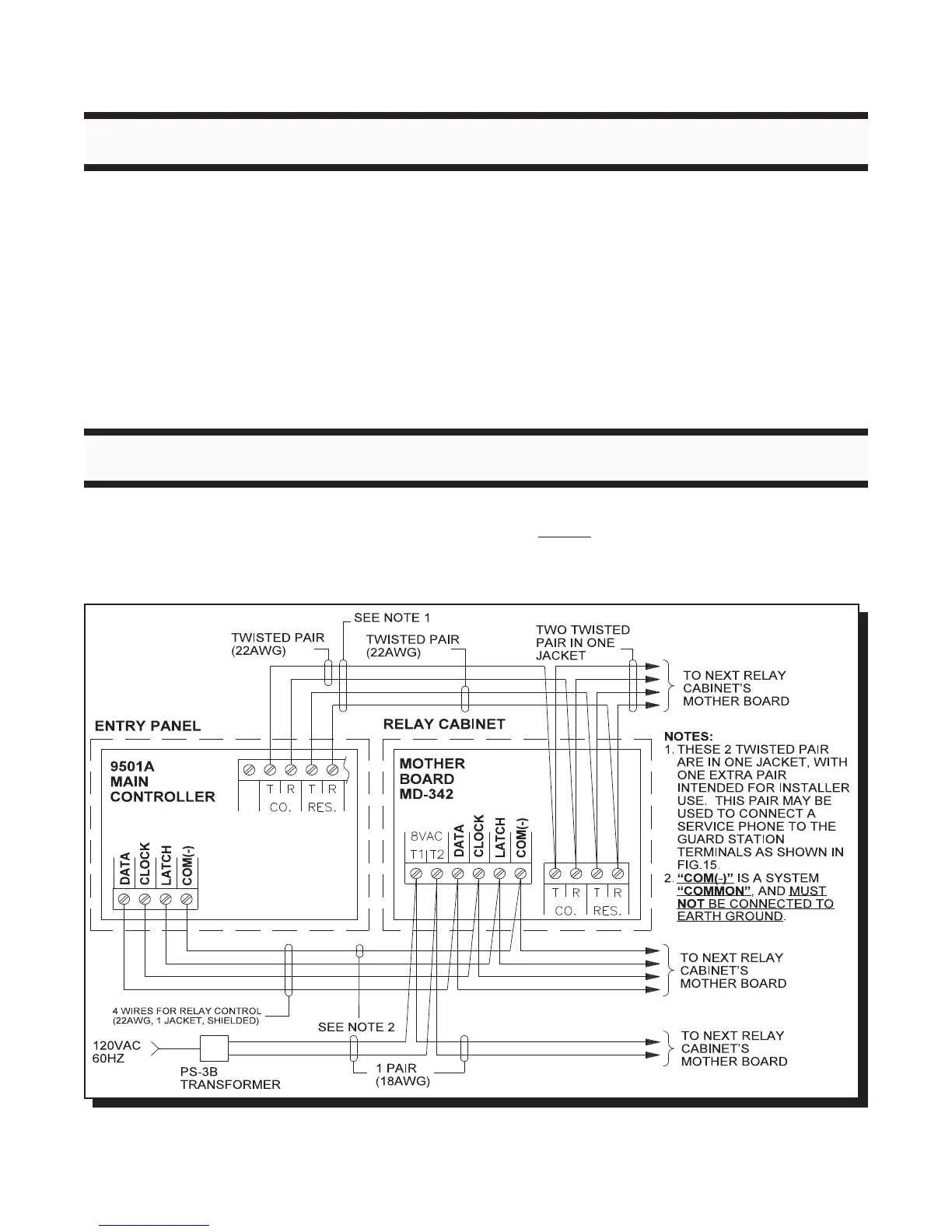
WIRING THE 9501A (Main Controller) TO 9508 or 9516 (Relay Cabinets)
Note that the Relay Control wiring (Data, Clock, Latch, Gnd) needs to be shielded 4-wire 22AWG cable. The shields must be
connected to Earth Ground at each terminating point. Also note that the Relay Control line “COM(-)” (marked “GND” on some
older boards) is a system “Common” and MUST NOT be connected to Earth Ground !
FIG.5 COMMUNICATION LINK WIRING

 Loading...


