MIRCOM TECHNOLOGIES LIMITED, 9500 Series: No Subscriber Line Page 24
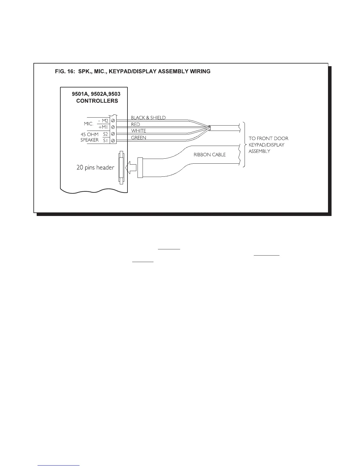
WIRING THE SPEAKER, MIC., and KEYPAD/DISPLAY ASSEMBLY TO 9501A, 9502A, or 9503 (Controllers)
Wire as shown in FIG. 16.
WIRING TO EARTH GROUND
Although the electronics of the 9500 Series System are not Earth Grounded, it is absolutely vital to have good solid Earth
Grounding connections to each enclosure; that is, a separate (do not rely on the Relay Control Wire shields to provide this
Earth Ground) ground bonding wire (preferably at least 14 AWG) that is run to the NEAREST confirmed building electrical
system ground, or cold water pipe. This is required on the 9501A, 9502A, and 9503 Lobby Panel Enclosures, and the
Decoder / Relay Cabinet(s). Newer enclosures will have a clearly marked screw connection on the back marked “CHASSIS
GROUND”. Older enclosures may be Earth Grounded via a mounting screw if the enclosure metal under the screw is sanded
clean of paint to ensure a good electrical connection.
The Relay Control Wires (see Fig.5) use 4-conductor shielded cable. At each wiring point (9501A and each MD-342 Relay
Mother Board) the cable shields are connected to the same Earth Ground as the enclosure. This Earth Ground MUST NOT
be connected to any of the four Relay Control Wires (Data, Clock, Latch, Com) themselves.
NOTE: IF PROPER GROUNDING REQUIREMENTS ARE NOT FOLLOWED AS OUTLINED, REPAIRS MAY NOT BE
COVERED BY WARRANTY.
WIRING THE DEDICATED TELEPHONE LINE
Connect the “Outside Line” modular jack to a touch tone (DTMF) type telephone line by using the supplied telephone cord.
The “Outside Line” modular jack is located on the upper-left corner of the 9501A main controller board. The outside line is
used by the system to autodial up to 11-digit telephone number through the telephone network.
POWERING THE SYSTEM
Before powering the system, double check all the connections. When all connections are checked, power the system up and
observe the system display. If necessary, adjust the contrast as described in the Display Contrast Adjustment section.

 Loading...


