MIRCOM TECHNOLOGIES LIMITED, 9500 Series: No Subscriber Line Page 19
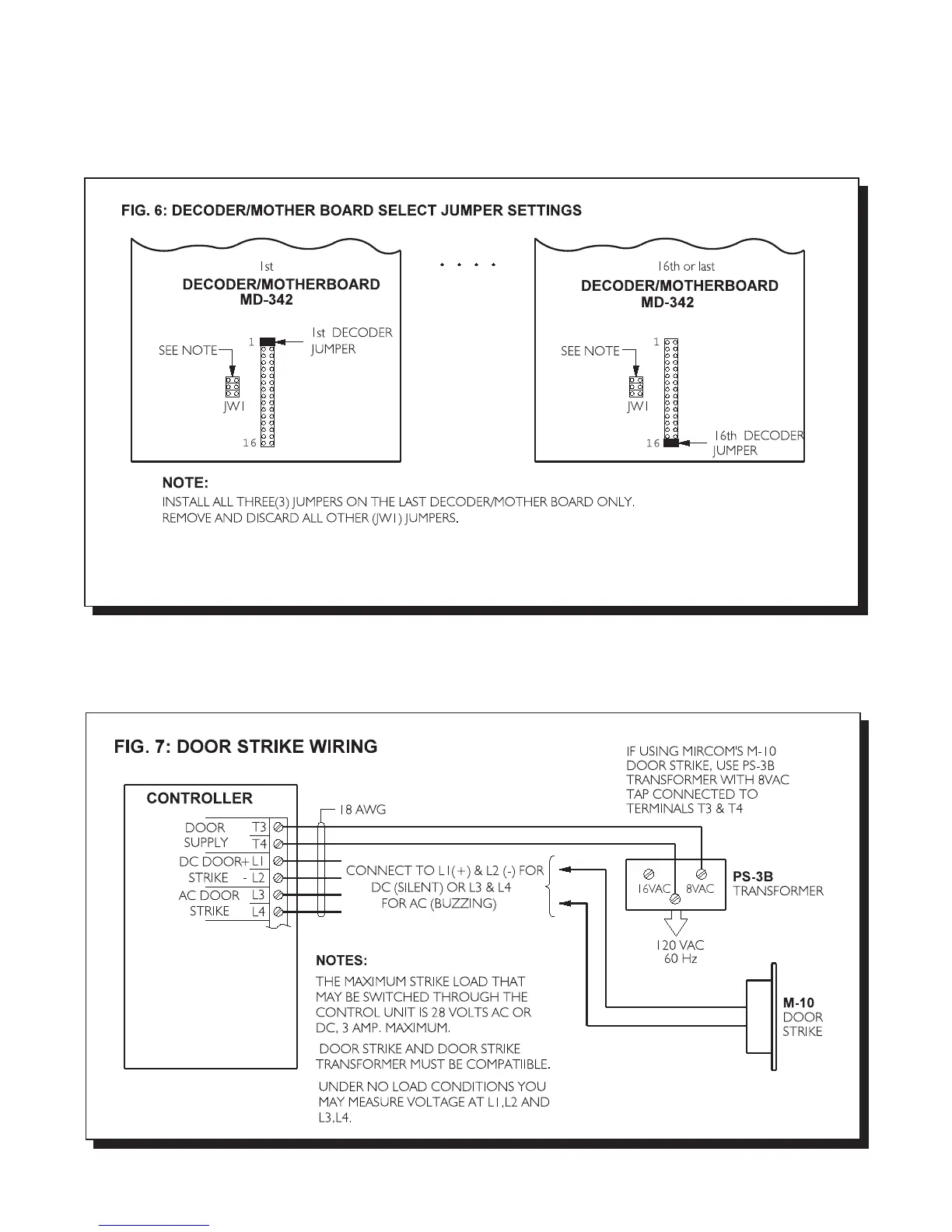
RELAY CABINET'S DECODER/MOTHER BOARD JUMPER CONFIGURATION
Install jumpers as shown in FIG. 6.
WIRING THE DOOR STRIKE TO 9501A, 9502A, or 9503 (Controllers)
Wire the Door Strike as shown in FIG. 7.

 Loading...


