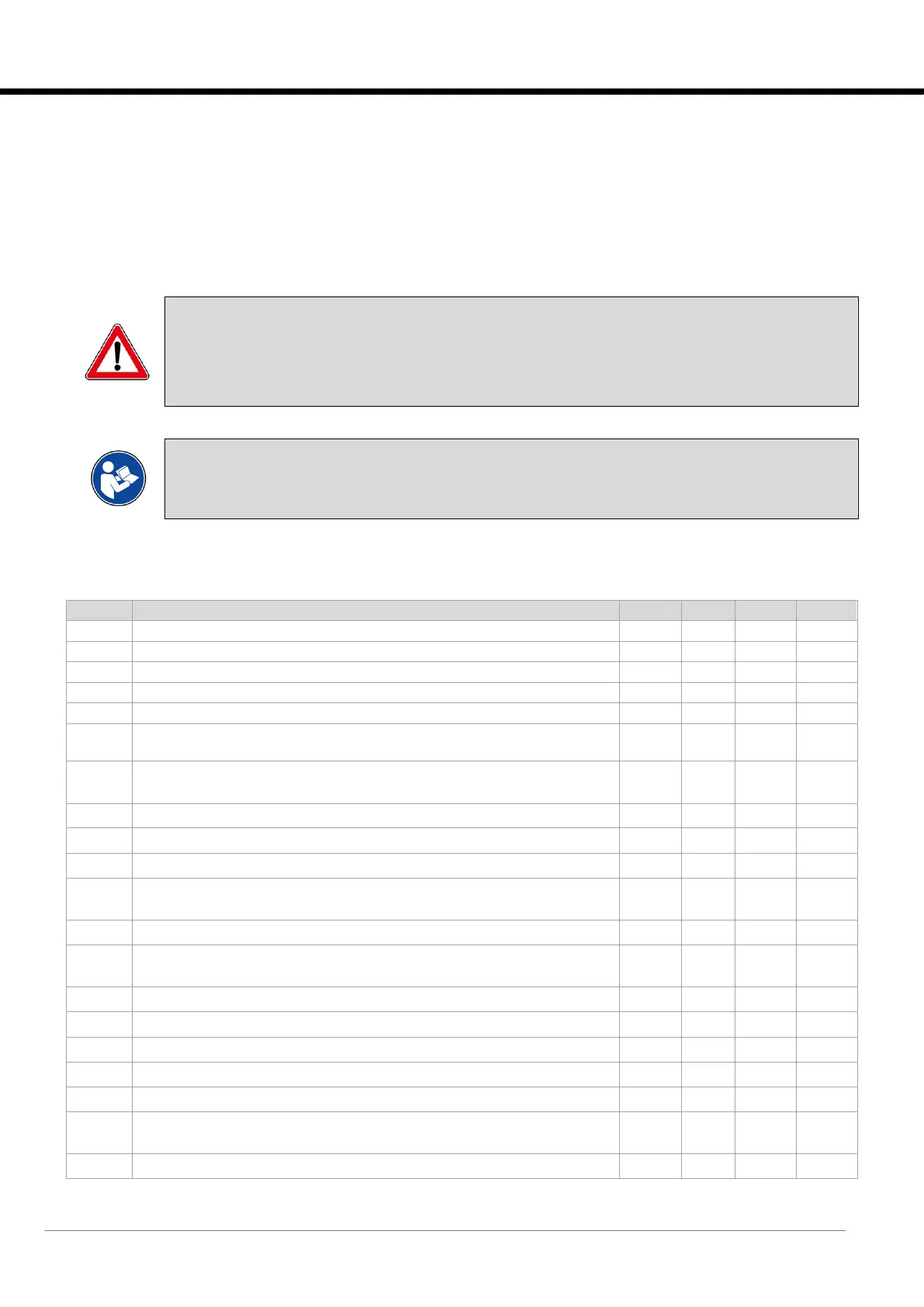
2.6 Parameter Table
The numbering of the parameters is divided by menu:
• 1x corresponds to the menus of the “Factory” group;
• 2x corresponds to the menus of the “Service” group;
• 3x corresponds to the menus of the “User” group;
• 50 corresponds to the “Setpoint” menu;
• 900 corresponds to the “Clock” menu.
The following table lists the controller parameters and the relative maximum and minimum values.
WARNING:
The “Default” column of the following table shows only the values assigned to the parameters using the
default procedure.
Changing the value of some parameters causes the value of others to change automatically. It is therefore
advisable to check all the parameters again after changes are made.
INFORMATION:
The parameter table shows all the parameters managed by the software, ensuring alignment with
the content of the files stored after the running tests.
Internal fan project speed
Internal fan minimum project speed (Maximum project speed reduction)
Start scale value of differential pressure transducer
End scale value of differential pressure transducer
Configuration of the external T probe on I/O PCO (0:Disabled – 1:Enabled)
Initial logo (0: Evolution – 1:De' Longhi – 2:ICS - 3:Neutral – 4:EATON –
5:Mitsubishi RC)
Unit type (0:Perimetral – 1:Rack Cooler – 2:Cooling Door – 3:Modular
Perimetral – 4:TLC)
Number of chilled water circuits
Enable indirect Free Cooling (0:Disabled – 1:Enabled)
Number of direct expansion circuits
Type of condensing unit (0:None/ t – Mate – 1:HCAT/i-HCAT – 2:m-MOCU
– 3:sMEXT)
Minimum off time of MR SLIM units
Internal unit model for MultiDensity (0:Reserved – 1:m-ROW009 – 2:m-
ROW015 – 3:m-ROW025 – 4:Reserved – 5:Reserved)
Number of compressors for circuit 1
Number of compressors for circuit 2
Internal fan project speed
Internal fan minimum project speed (Maximum project speed reduction)
Type of Gas (0:R410A – 1:R32)
Presence of low pressure transducer on base board (0:Disabled –
1:Enabled)
Type of signal for pCOOEM+ for LP probe [0=0-5VRat | 1=4-20mA]






 To Next Page