APPX
Appendix 3 Buffer Memory Areas
125
A
Appendix 3 Buffer Memory Areas
List of buffer memory addresses
The following table lists the buffer memory addresses of the A/D converter module. For details on the buffer memory
addresses, refer to the following.
Page 146 Details of buffer memory addresses
The buffer memory areas of the A/D converter module are classified by the following data types.
• Do not write data to the system areas and areas whose data types are monitor in the buffer memory. Writing
data into these areas can cause the malfunction of the module.
• When the R60AD8-G is used, the areas corresponding to CH9 to CH16 are used as system areas.
In R mode
■Un\G0 to Un\G399
Data type Description
Setting data Description Set this data according to the connected device and the use of the system.
Write/read attribute Data can be read and written from/to this area.
Setting procedure Set this data using an engineering tool or in a program.
Setting timing After changing the values, turn on and off 'Operating condition setting request' (Y9) to enable the
set values.
Control data Description Use this data to control the A/D converter module.
Write/read attribute Data can be read and written from/to this area.
Setting procedure Set this data using an engineering tool or in a program.
Setting timing As soon as the values are changed, the set values become enabled.
Monitor data Description Use this data to monitor the status of the A/D converter module.
Write/read attribute Writing data is only allowed. Reading data is not allowed.
Setting procedure
Setting timing
User range setting data Description Use this data to update the user range setting of the A/D converter module.
Write/read attribute Data can be read and written from/to this area.
Setting procedure Set this data using an engineering tool or in a program.
Setting timing After changing the values, turn on and off 'User range write request' (YA) to enable the set
values.
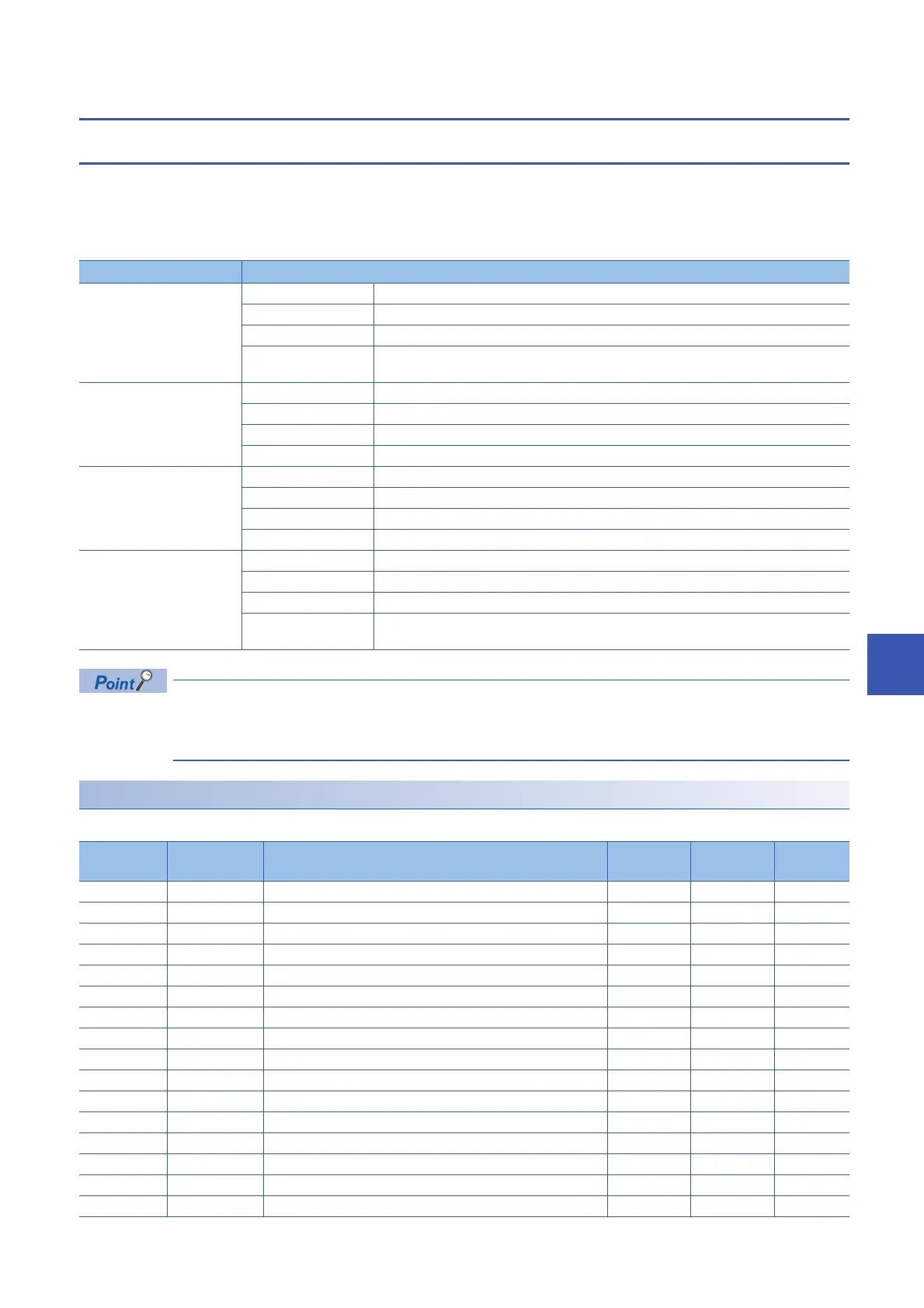
Address
(decimal)
Address
(hexadecimal)
Name Default
value
Data type Auto
refresh
0 0H Latest error code 0 Monitor
1 1H Latest address of error history 0 Monitor
2 2H Latest alarm code 0 Monitor
3 3H Latest address of alarm history 0 Monitor
4 to 19 4H to 13H Interrupt factor detection flag [n]
*1
0 Monitor
20 to 35 14H to 23H System area
36 24H Alert output flag (Process alarm upper limit) 0000H Monitor
37 25H Alert output flag (Process alarm lower limit) 0000H Monitor
38 26H Alert output flag (Rate alarm upper limit) 0000H Monitor
39 27H Alert output flag (Rate alarm lower limit) 0000H Monitor
40 28H Input signal error detection flag 0000H Monitor
41 29H System area
42 2AH A/D conversion completed flag 0000H Monitor
43 to 89 2BH to 59H System area
90 5AH Level data 0 0 Control
91 5BH Level data 1 0 Control
 Loading...


