236
8 SYSTEM CONFIGURATION
8.1 Redundant Master Station
8.1 Redundant Master Station
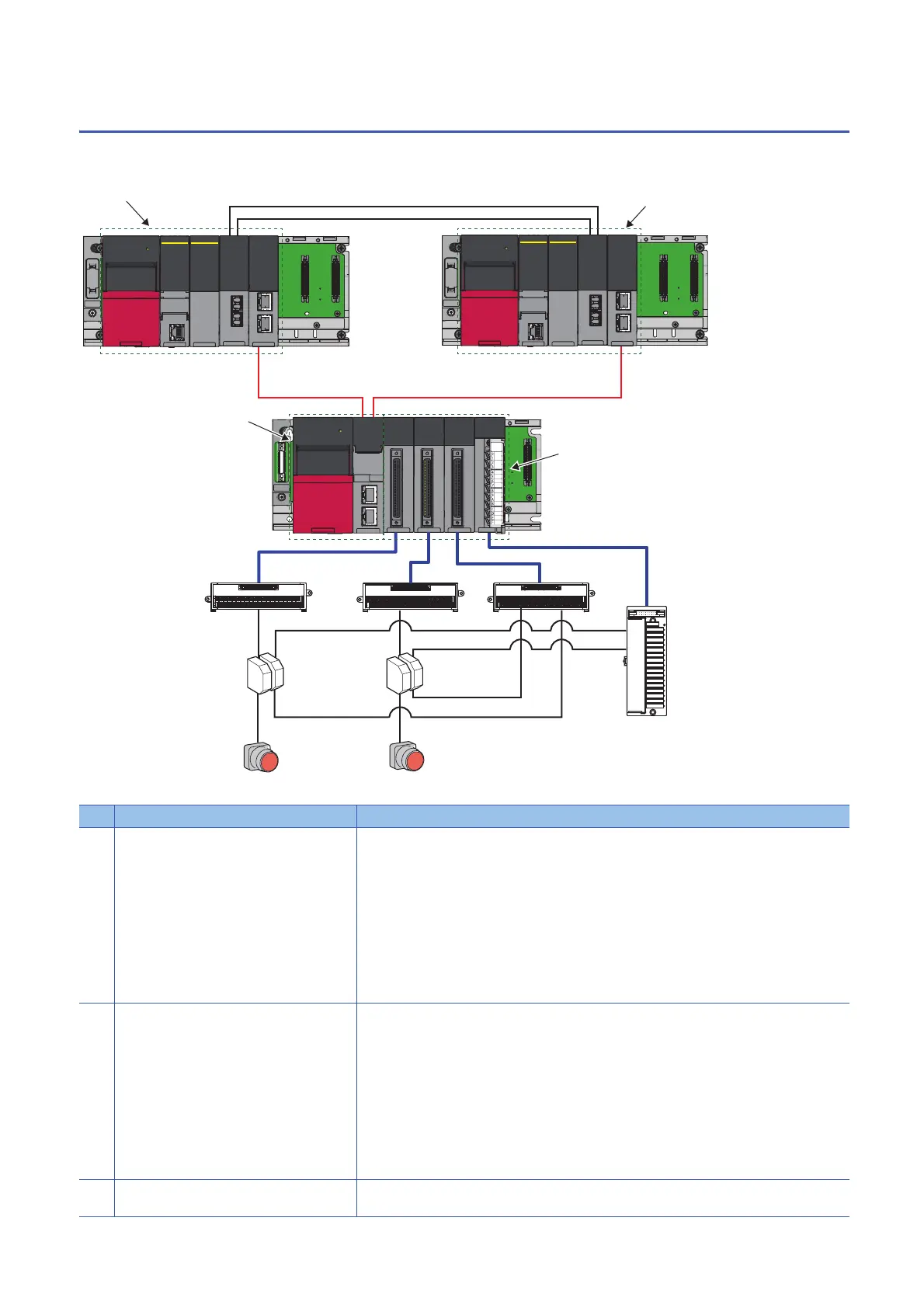
The following diagram shows the system configuration with a redundant master station.
• System configuration diagram
• List of components
No. Name Description
(1) System A system Composed of the following modules:
• RnPSFCPU
• R6PSFM
•R6RFM
• RJ71GF11-T2
■Precautions
• Each module has restrictions on use in a system on the system configuration diagram. For details,
refer to the User's Manual (Application) for each module.
• Mount the above modules on the same base. Mount the modules so that they are arranged in the
following order: RnPSFCPU R6PSFM R6RFM RJ71GF11-T2, starting from the right side
of the power supply module.
(2) System B system Composed of the following modules:
• RnPSFCPU
• R6PSFM
•R6RFM
• RJ71GF11-T2
■Precautions
• Each module has restrictions on use in a system on the system configuration diagram. For details,
refer to the User's Manual (Application) for each module.
• Mount the above modules on the same base. Mount the modules so that they are arranged in the
following order: RnPSFCPU R6PSFM R6RFM RJ71GF11-T2, starting from the right side
of the power supply module.
(3) Tracking cable Use cables designed for use by the R6RFM. ( MELSEC iQ-R CPU Module User's Manual
(Startup))
(1)
(2)
(3)
(3)
(5)
(4) (4)
(6)
(8)
(7) (7)
(8)
(10)
(9)
(12)
(11)
(13)
(13)
 Loading...


