FULL-AUTOMATIC AIR CONDITIONER – Troubleshooting
55-55
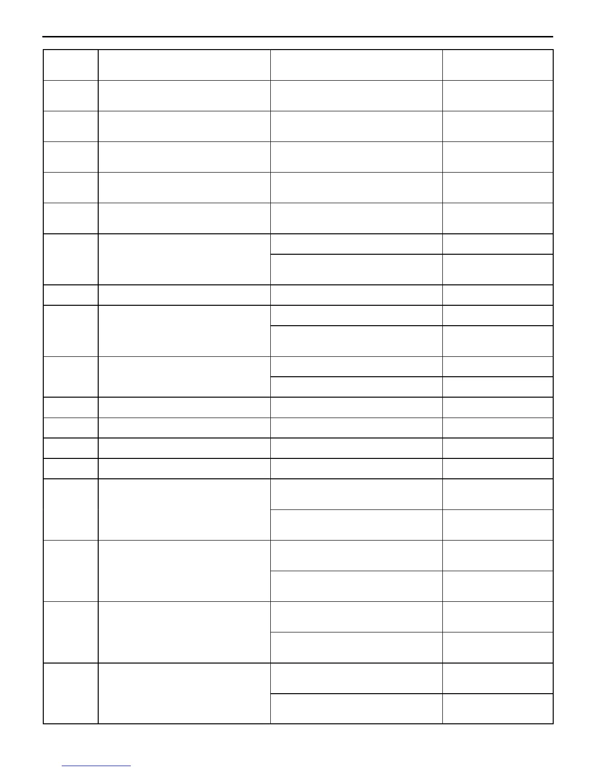
Terminal
No.
Normal conditionCheck conditionCheck item
4 Heater water temperature sensor
input
When sensor section temperature is
25_C (4 kΩ)
2.3 – 2.9 V
5 Air mix damper potentiometer input When damper is moved to MAX. HOT
position
4.7 – 5.0 V
6 Air outlet changeover damper poten-
tiometer input
When damper is moved to DEF.
position
4.8 – 5.2 V
7 Outside air temperature sensor input When sensor section temperature is
25_C (4 kΩ)
2.3 – 2.9 V
8 Air thermo sensor input When sensor section temperature is
25_C (4 kΩ)
2.3 – 2.9 V
9 Photo sensor (–) At luminous intensity of 0 lux 0 V
At luminous intensity of 100,000 lux or
more
–0.1 – 0.2 V
10 Sensor power supply At all times 4.8 – 5.2 V
12 Blower motor HI relay (Exciting circuit) When blower switch is in HI 1.5 V or less
When blower switch is in a position
other than HI
System voltage
16 Rear defogger When rear defogger switch is ON 1.5 V or less
When rear defogger switch is OFF System voltage
17 Diagnosis date output When ignition switch is ON 0 V ↔ 12 V
18 Diagnosis control output When ignition switch is ON System voltage – 2 V
19 Photo sensor (+) At all times 0 V
20 Sensor earth At all times 0 V
21 Air outlet changeover damper motor
(FACE)
When damper is moved to FACE
position
10 V
When damper is moved to DEF.
position
Almost no voltage
(0.5 V)
22 Air mix damper motor (MAX. COOL) When damper is moved to MAX.
COOL position
10 V
When damper is moved to MAX. HOT
position
Almost no voltage
(0.5 V)
23 Inside/outside air changeover damper
motor (Inside)
When switch is set to inside air
position
Almost no voltage
(0.5 V)
When switch is set to outside air
position
10 V
24 Air outlet changeover damper motor
(DEF.)
When damper is moved to FACE
position
Almost no voltage
(0.5 V)
When damper is moved to DEF.
position
10 V


 To Next Page