FULL-AUTOMATIC AIR CONDITIONER – Troubleshooting
55-54
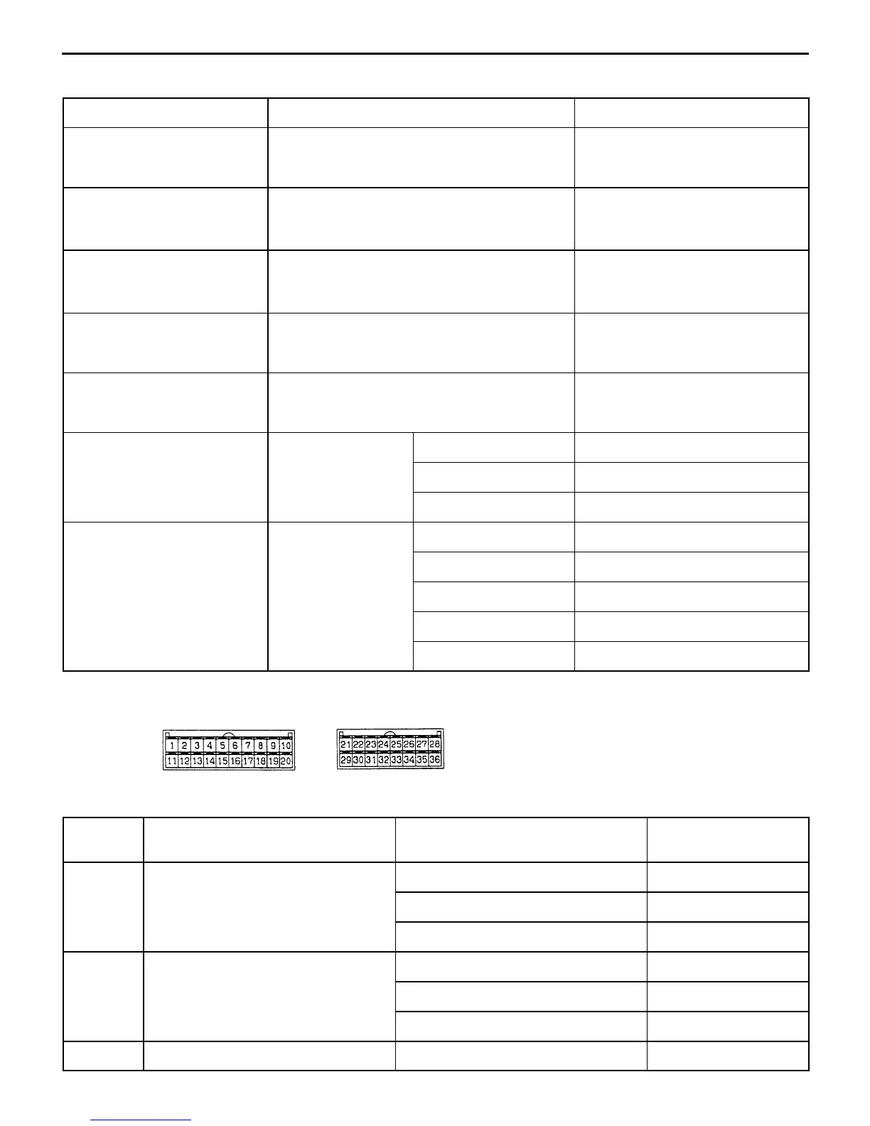
DATA LIST REFERENCE TABLE
Check item Check condition Normal condition
Inside air temperature sensor
D MUT-II (11)
Ignition switch: ON Inside air temperature and temper-
ature displayed on the MUT-II are
identical.
Outside air temperature sen-
sor
D MUT-II (13)
Ignition switch: ON Outside air temperature and tem-
perature displayed on the MUT-II
are identical.
Heater water temperature
sensor
D MUT-II (15)
Ignition switch: ON Heater core surface temperature
and temperature displayed on the
MUT-II are identical.
Air thermo sensor
D MUT-II (21)
Ignition switch: ON Evaporator surface temperature
and temperature displayed on the
MUT-II are identical.
Photo sensor
D MUT-II (25)
Ignition switch: ON Amount of incident light is propor-
tional to voltage displayed on the
MUT-II.
Air mix damper potentiometer
Ignition switch: ON Damper position Opening degree (%)
D
-
MAX. HOT Approx. 100
MAX. COOL Approx. 0
Air outlet changeover damper
Ignition switch: ON Damper position Opening degree (%)
D MUT-II (32)
FACE Approx. 0
FOOT Approx. 50
FOOT/DEF. Approx. 75
DEF. Approx. 100
CHECK AT THE A/C-ECU TERMINALS
A/C-ECU
The parenthesized values in “Normal condition” column are for your reference.
Terminal
No.
Check item Check condition Normal condition
1 Front power transistor collector output When blower switch is at OFF System voltage
When blower switch is at LO Approx. 7 V
When blower switch is at HI Almost no voltage (0 V)
2 Front power transistor base output When blower switch is at OFF 0 V
When blower switch is at LO Approx. 1.3 V
When blower switch is at HI Approx. 2.5 V
3 Backup At all times System voltage



 To Next Page