3 - 4 3 - 4
MELSEC-Q
3 SPECIFICATIONS
3.3 I/O signals for Programmable Controller CPU
3.3.1 List of I/O signals
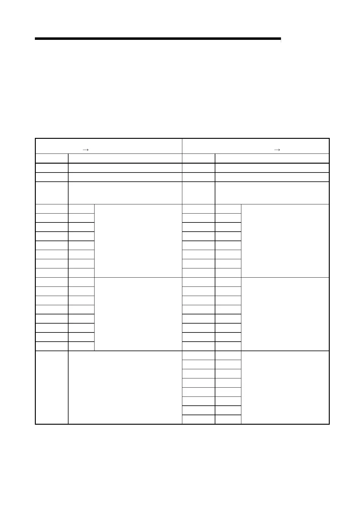
The following table indicates the I/O signals of the QD60P8-G for the programmable
controller CPU.
The I/O numbers (X/Y) and I/O addresses indicated in this chapter and later assume
that the QD60P8-G is installed on the I/O slot No. 0 of the main base unit.
Input signal (Signal direction:
QD60P8-G
programmable controller CPU)
Output signal (Signal direction:
programmable controller CPU QD60P8-G)
Device No. Signal name Device No. Signal name
X0 Module READY Y0 Reserved (N/A) *
X1 Operating condition setting complete flag Y1 Operating condition setting request flag
X2
to
X7
Reserved (N/A) *
Y2
to
Y7
Reserved (N/A) *
X8 CH1 Y8 CH1
X9 CH2 Y9 CH2
XA CH3 YA CH3
XB CH4 YB CH4
XC CH5 YC CH5
XD CH6 YD CH6
XE CH7 YE CH7
XF CH8
Error occurrence
YF CH8
Error reset request
X10 CH1 Y10 CH1
X11 CH2 Y11 CH2
X12 CH3 Y12 CH3
X13 CH4 Y13 CH4
X14 CH5 Y14 CH5
X15 CH6 Y15 CH6
X16 CH7 Y16 CH7
X17 CH8
Accumulating counter comparison
flag
Y17 CH8
Comparison signal reset request
Y18 CH1
Y19 CH2
Y1A CH3
Y1B CH4
Y1C CH5
Y1D CH6
Y1E CH7
X18
to
X1F
Reserved (N/A) *
Y1F CH8
Count enable
*: Write is inhibited to the I/O (X/Y) reserved for the system.
 Loading...