5 - 3 5 - 3
MELSEC-Q
5 DETAILS AND SETTING OF FUNCTIONS
5.1.3 Count value reading
This section explains how to read the count values (sampling pulse number,
accumulating count value, input pulse value) stored in the buffer memory.
The accumulating count value and input pulse value are stored in the buffer memory
as two words (32 bits). When reading the count value from the module, always read
two words together.
The buffer memory addresses where the count values are stored are as follows.
Buffer memory address
Item
CH1 CH2 CH3 CH4 CH5 CH6 CH7 CH8
Sampling pulse number 0 32 64 96 128 160 192 224
Accumulating count value
8
9
40
41
72
73
104
105
136
137
168
169
200
201
232
233
Input pulse value
10
11
42
43
74
75
106
107
138
139
170
171
202
203
234
235
The buffer memory addresses of the counter reset requests for resetting the count
values are as follows.
Buffer memory address
Item
CH1 CH2 CH3 CH4 CH5 CH6 CH7 CH8
Counter reset request 13 45 77 109 141 173 205 237
The update timings of the count values are as follows.
Item Update timing
Sampling pulse number
Accumulating count value
Count cycle setting value (Refer to Section 5.1.4)
Input pulse value 10ms
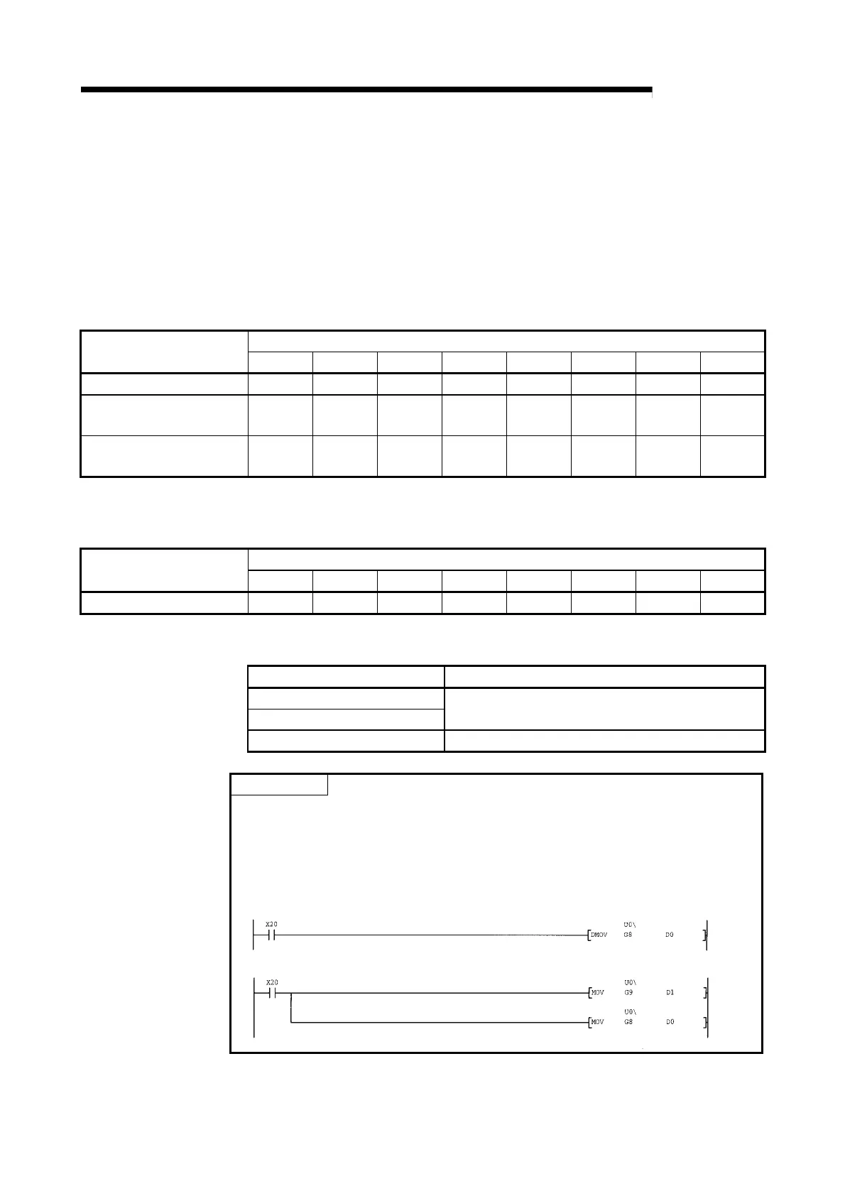
POINT
When reading the accumulating count value or input pulse value, always read two
words together.
If it is read in single word unit, a wrong count value may be read due to a data
mismatch between the lower word and upper word when the count value is
updated halfway during read.
[Program example]
[Incorrect program example]
 Loading...