3 - 14 3 - 14
MELSEC-Q
3 SPECIFICATIONS
3.5 Interface with External Devices
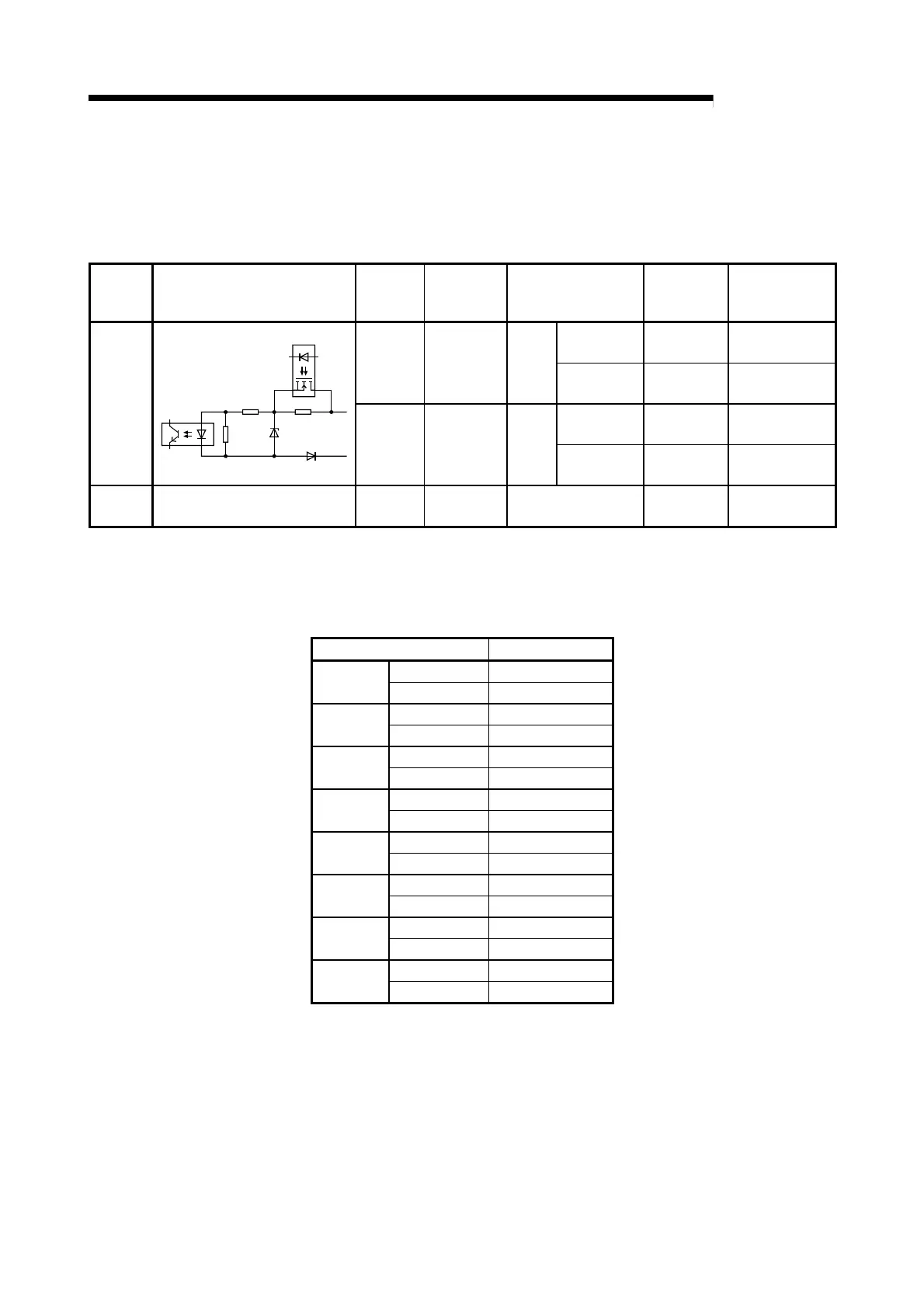
The internal circuit of the QD60P8-G interface for connection of external devices is
shown in a schematic diagram.
Input/
Output
Internal circuit
Terminal
number
Signal name Operation
Input voltage
(guaranteed
value)
Operating current
(guaranteed
value)
5VDC * 3.5V to 5.5V 4mA or more
1, 3, 5, 7,
9, 11,
13, 15
CH1 to 8 V+ At ON
12 to 24VDC * 10.2 to 30V 4mA or more
5VDC * 1.0V or less 0.5mA or less
Input
2, 4, 6, 8,
10, 12,
14, 16
CH1 to 8 V- At OFF
12 to 24VDC * 2.0V or less 0.5mA or less
- -
17
18
FG - - -
*: Use the intelligent function module switch to change between 5VDC and 12 to 24VDC.
(For details, refer to "Section 4.5 Switch setting for intelligent function module".)
Signal layout of each channel
Terminal number Signal name
1 CH1 V+
CH1
2 CH1 V-
3 CH2 V+
CH2
4 CH2 V-
5 CH3 V+
CH3
6 CH3 V-
7 CH4 V+
CH4
8 CH4 V-
9 CH5 V+
CH5
10 CH5 V-
11 CH6 V+
CH6
12 CH6 V-
13 CH7 V+
CH7
14 CH7 V-
15 CH8 V+
CH8
16 CH8 V-
 Loading...