3 - 5 3 - 5
MELSEC-Q
3 SPECIFICATIONS
3.3.2 Details of I/O signals
The I/O signals of the QD60P8-G are detailed below.
(1) Details of input signals (QD60P8-G programmable controller
CPU)
The following table indicates the ON/OFF timings and functions of the input
signals.
Device
No.
Signal name Details
Initial
value
*1
X0 Module READY
OFF: Not
Prepared/
Watch dog
timer error
ON : Prepared
• This signal judges whether the QD60P8-G is normal or
abnormal in the sequence program. This signal turns ON
when the module starts normally at power-on or reset
operation.
• This signal turns OFF at occurrence of a watch dog timer
error.
OFF
X1
Operating
condition setting
complete flag
OFF: Operating
condition
setting
ON : Operating
condition
setting
complete
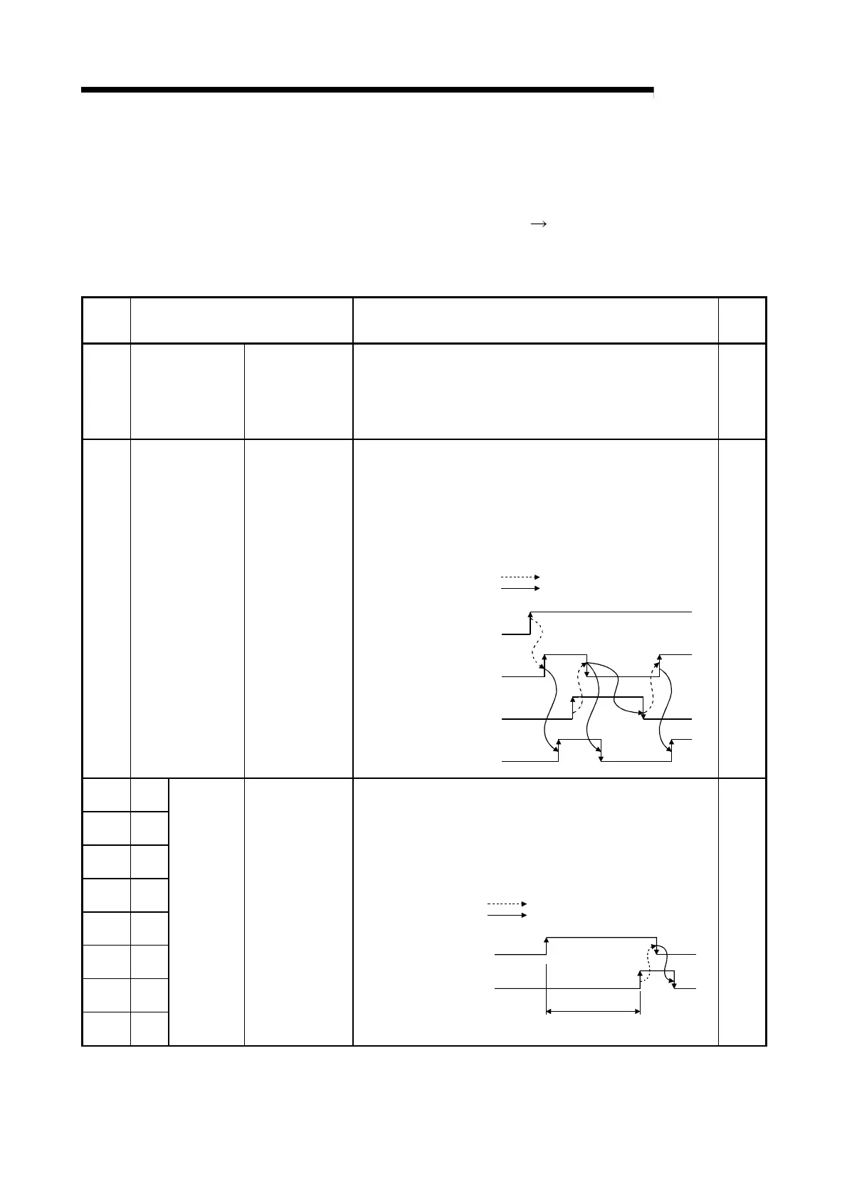
• This signal is used as an interlock for turning ON/OFF the
operating condition setting request flag (Y1) when the function,
such as the comparison output function, is selected or the
setting value is changed.
• When this signal is OFF, input pulses are not counted.
• After confirming that the operating condition setting is
completed (this signal has turned ON), turn ON the count
enable signal (Y18 to Y1F) to start pulse counting.
Operating condition
setting request flag
Operating condition
setting complete flag
Module
READY
OFF
ON
OFF
ON
OFF
OFF
ON
(X0)
(X1)
(Y1)
(Y18 to Y1F)
ON
Executed by QD60P8-G
Count enable
Executed by sequence program
OFF
X8 CH1
X9 CH2
XA CH3
XB CH4
XC CH5
XD CH6
XE CH7
XF CH8
Error
occurrence
OFF: No error
occurrence
ON : Error
occurrence
• This signal turns ON if an error exists in the overflow detection
or initial setting data. (The details of the error can be confirmed
from the "system monitor" screen of GX Developer.)
• This signal turns OFF when the error reset request (Y8 to YF)
is turned ON.
• The "error code" is stored into the buffer memory of the
corresponding channel (refer to Section 3.4.2 for details).
Error occurrence
(X8 to XF)
Error code is read during this period.
Executed by QD60P8-G
OFF
ON
OFF
ON
Error reset request
(Y8 to YF)
Executed by sequence program
OFF
*1: Initial value set at power-on or when the programmable controller CPU is reset.
 Loading...