3 - 8 3 - 8
MELSEC-Q
3 SPECIFICATIONS
3.4 Buffer Memory
3.4.1 List of buffer memory assignments
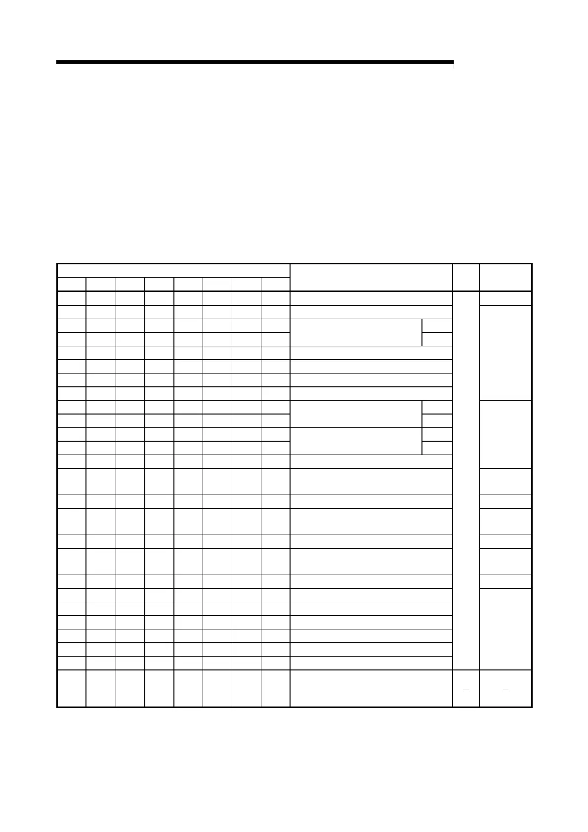
The following table indicates the assignment of the QD60P8-G buffer memory. Refer to
Section 3.4.2 for details of the buffer memory areas.
The initial values are set to the buffer memory at power-on or when the programmable
controller CPU is reset. (When power is switched OFF, the setting values in the buffer
memory are not retained.)
The sequence program or programmable controller CPU's auto refresh function,
reads/writes the buffer memory contents.
The settings are reflected on the module by turning ON the operating condition setting
request flag (Y1) after the data have been written to the buffer memory.
Buffer memory address
CH1 CH2 CH3 CH4 CH5 CH6 CH7 CH8
Setting details
Initial
value
Read/Write
0 32 64 96 128 160 192 224 Sampling pulse number Read only
1 33 65 97 129 161 193 225 Comparison output selection
2 34 66 98 130 162 194 226 (L)
3 35 67 99 131 163 195 227
Comparison output setting value
(H)
4 36 68 100 132 164 196 228 Movement averaging processing selection
5 37 69 101 133 165 197 229 Number of movement averaging processing
6 38 70 102 134 166 198 230 Pre-scale function selection
7 39 71 103 135 167 199 231 Pre-scale setting value
Read/Write
enabled
8 40 72 104 136 168 200 232 (L)
9 41 73 105 137 169 201 233
Accumulating count value
(H)
10 42 74 106 138 170 202 234 (L)
11 43 75 107 139 171 203 235
Input pulse value
(H)
12 44 76 108 140 172 204 236 Overflow detection flag
Read only
13 45 77 109 141 173 205 237 Counter reset request
Read/Write
enabled
14 46 78 110 142 174 206 238 Carry over detection flag Read only
15 47 79 111 143 175 207 239 Carry over reset request
Read/Write
enabled
16 48 80 112 144 176 208 240 Error code Read only
17 49 81 113 145 177 209 241 Alarm output selection
Read/Write
enabled
18 50 82 114 146 178 210 242 Alarm output flag Read only
19 51 83 115 147 179 211 243 Alarm output setting value upper/upper limit
20 52 84 116 148 180 212 244 Alarm output setting value upper/lower limit
21 53 85 117 149 181 213 245 Alarm output setting value lower/upper limit
22 54 86 118 150 182 214 246 Alarm output setting value lower/lower limit
23 55 87 119 151 183 215 247 Count cycle change function selection
24 56 88 120 152 184 216 248 Count cycle setting value
0
Read/Write
enabled
25 57 89 121 153 185 217 249
to to to to to to to to
31 63 95 127 159 191 223 255
Reserved (N/A)
*1: Initial value set at power-on or when the programmable controller CPU is reset.
 Loading...