4 - 6 4 - 6
MELSEC-Q
4 SETUP AND PROCEDURE BEFORE OPERATION
4.4.2 Wiring example
This section shows an example of wiring the QD60P8-G and pulse generator.
In the wiring example of this section, only CH1 is wired. Also, in this example, the
voltage of the external power supply is 24VDC as the electrical specifications of the
pulse generator.
!
DANGER
• When wiring, be sure to verify the rated voltage of the product as well as the terminal layout.
Fire or failure may result if incorrect voltage is input or incorrect wiring is performed.
• Do not apply the voltage exceeding the value set on the "Intelligent function module switch
setting" dialog box to the terminals.
Failure to observe this may cause fire or failure.
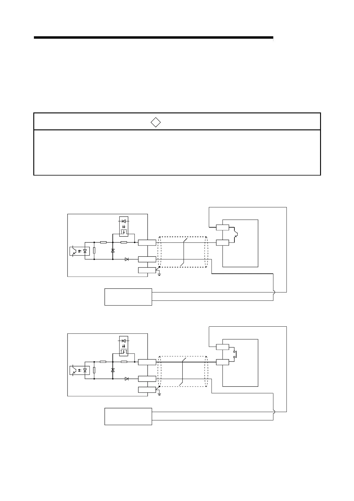
(1) Wiring example with a source logic type pulse generator
(a) For transistor output
24VDC
power supply
Pulse generator
CH1 V+
CH1 V-
FG
OUT
+24V
-
+
QD60P8-G
Shielded twisted pair cable
(b) For contact output
24VDC
power supply
Pulse generator
CH1 V+
CH1 V-
FG
OUT
+24V
-
+
QD60P8-G
Shielded twisted pair cable
 Loading...