5 - 16 5 - 16
MELSEC-Q
5 DETAILS AND SETTING OF FUNCTIONS
Outline of alarm output function operation
The following gives the outline of the alarm output function operation.
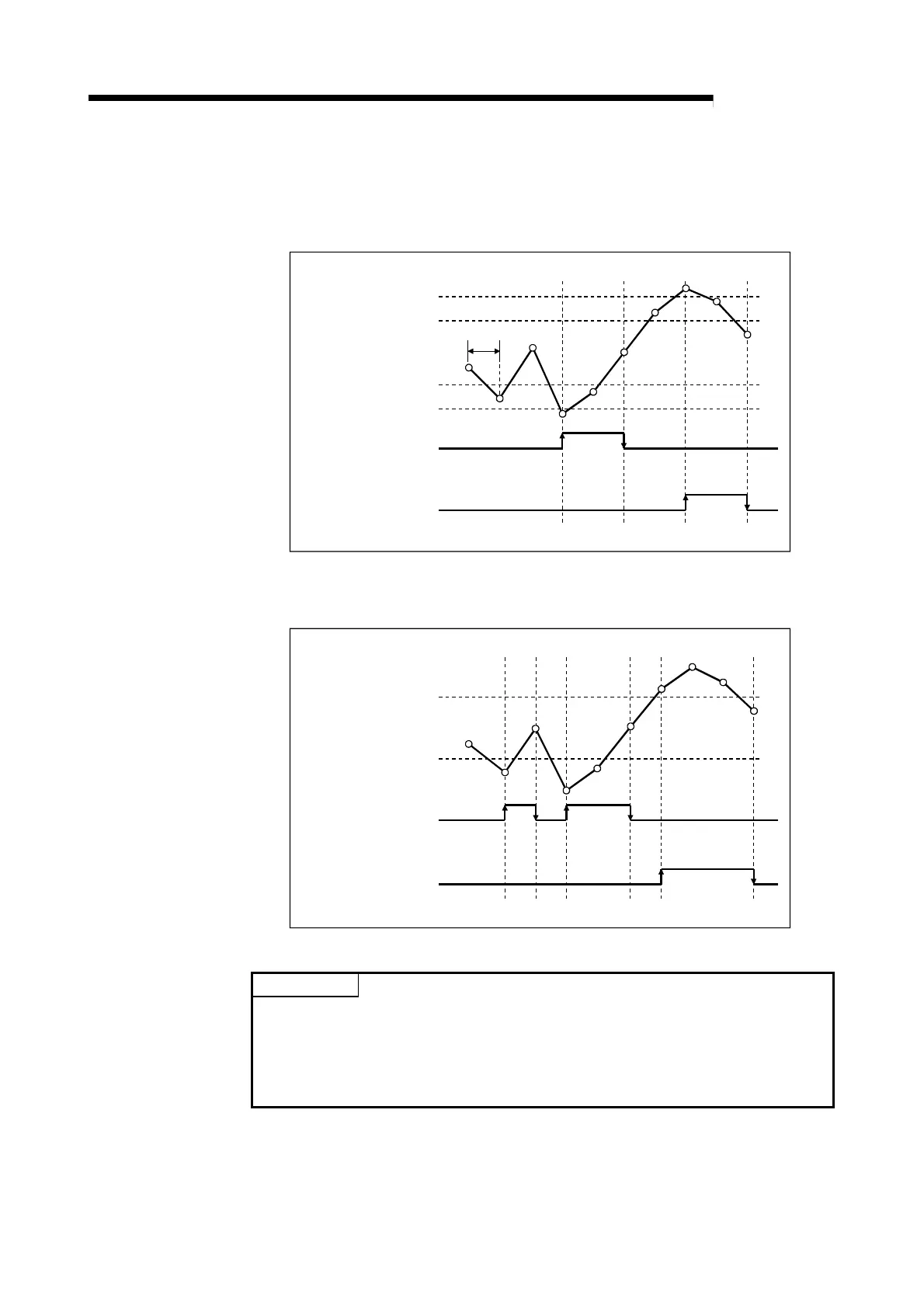
• Example of alarm output operation
Lower/ lower limit value
Lower/ upper limit value
Upper/ lower limit value
Upper/ upper limit value
ON
ON
OFF
OFF
Alarm output flag
bit0 (Lower limit alarm)
bit8 (Upper limit alarm)
Count cycle
• Assuming that the upper/upper limit = upper/lower limit and lower/upper limit =
lower/lower limit, operation is performed as shown below.
bit8 (Upper limit alarm)
Alarm output flag
bit0 (Lower limit alarm)
Lower/ upper limit value
Lower/ lower limit value
Upper/ upper limit value
Upper/ lower limit value
ON
ON
OFF
OFF
POINT
• Since the "sampling pulse number" of the buffer memory is updated at intervals
of the count cycle setting value (refer to Section 5.1.4), the alarm output flag also
turns ON/OFF at the timing of the count cycle setting value.
• The settings are reflected on the module by turning ON the operating condition
setting request flag (Y1) after setting the values to the buffer memory.
 Loading...