7 - 4 7 - 4
MELSEC-Q
7 PROGRAMMING
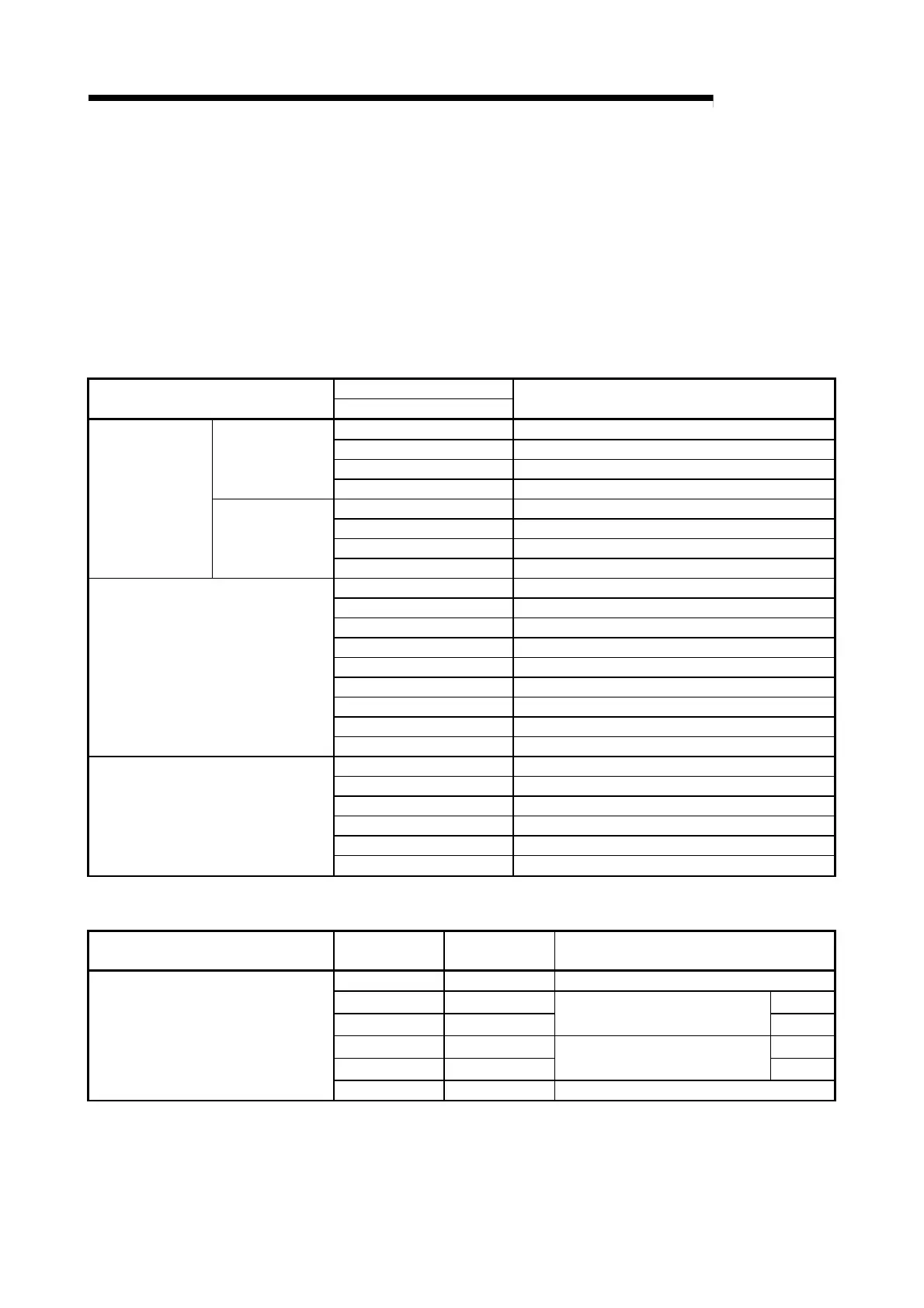
(3) List of devices used
In Section 7.2.1 program example, the used devices are assigned as indicated in
the following table.
The I/O numbers for QD60P8-G indicate those when QD60P8-G is mounted in
the 0-slot of the main base unit.
If it is mounted in the slot other than the 0-slot of the main base unit, change the
I/O number to that for the position where QD60P8-G was installed.
In addition, change the external inputs, internal relays and data resisters,
according to the system used.
Inputs/outputs, external inputs, and internal relays of QD60P8-G
Device
Device name
CH1
Application
X0 Module READY
X1 Operating condition setting complete flag
X8 Error occurrence
Inputs
X10 Accumulating counter comparison flag
Y1 Operating condition setting request flag
Y8 Error reset request
Y10 Comparison signal reset request
Input/output of
QD60P8-G
Outputs
Y18 Count enable
X20 Data setting command
X21 Count enable ON command
X22 Count enable OFF command
X23 Comparison signal reset command
X24 Error reset command
X25 Counter reset request command
X26 Sampling pulse number read command
X27 Accumulating count value read command
External input (command)
X28 Input pulse value read command
M10 Data setting enable
M11 Overflow detection flag
M30 Counter resetting
M40 Carry over detection flag
M60 Carry over resetting
Internal relay
M80 Alarm output flag
Data registers
Device name Device
Buffer memory
address
Data stored
D30 0 Sampling pulse number
D31 8 (L)
D32 9
Accumulating count value
(H)
D33 10 (L)
D34 11
Input pulse value
(H)
Data registers
D35 16 Error code
 Loading...