Setup Chapter Two: Installation
16
Setup
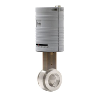
This section covers how to install the 649 controller into your system.
Fittings
The 649 pressure controller is available with the following fittings:
• Cajon 4-VCR male compatible
• Cajon 8-VCR male compatible
Mounting Hardware
The 649 controller has two mounting holes located on the bottom or base of the unit. Use #8-32
UNC-2B hardware to mount the unit. Refer to Figure 4, page 15, shows the location and
dimension of the mounting hole.
Gas Pressure
The control valve, housed inside the 649 controller enclosure, is rated for a maximum inlet
pressure of 150 psia [1034 kPa]. Ensure that the inlet pressure is consistent with the overpressure
limit of the pressure transducer. This will eliminate damage to the transducer should the valve
open fully. Refer to Applications with a Large Differential Pressure, page 31, for more
information.
The control valve is not a positive shutoff valve. Some leakage across the valve may occur.
Refer to Appendix A: Product Specifications, page 45, for the leak integrity specifications. If
necessary, install a separate positive shutoff valve in your system.
Caution
Take care not to expose the pressure transducer to pressures above its
full scale range. Pressures exceeding 45 psia [310 kPa] or twice the
full scale pressure (whichever is greater) may damage the pressure
transducer.