Chapter Three: Overview General Information
21
Chapter Three: Overview
General Information
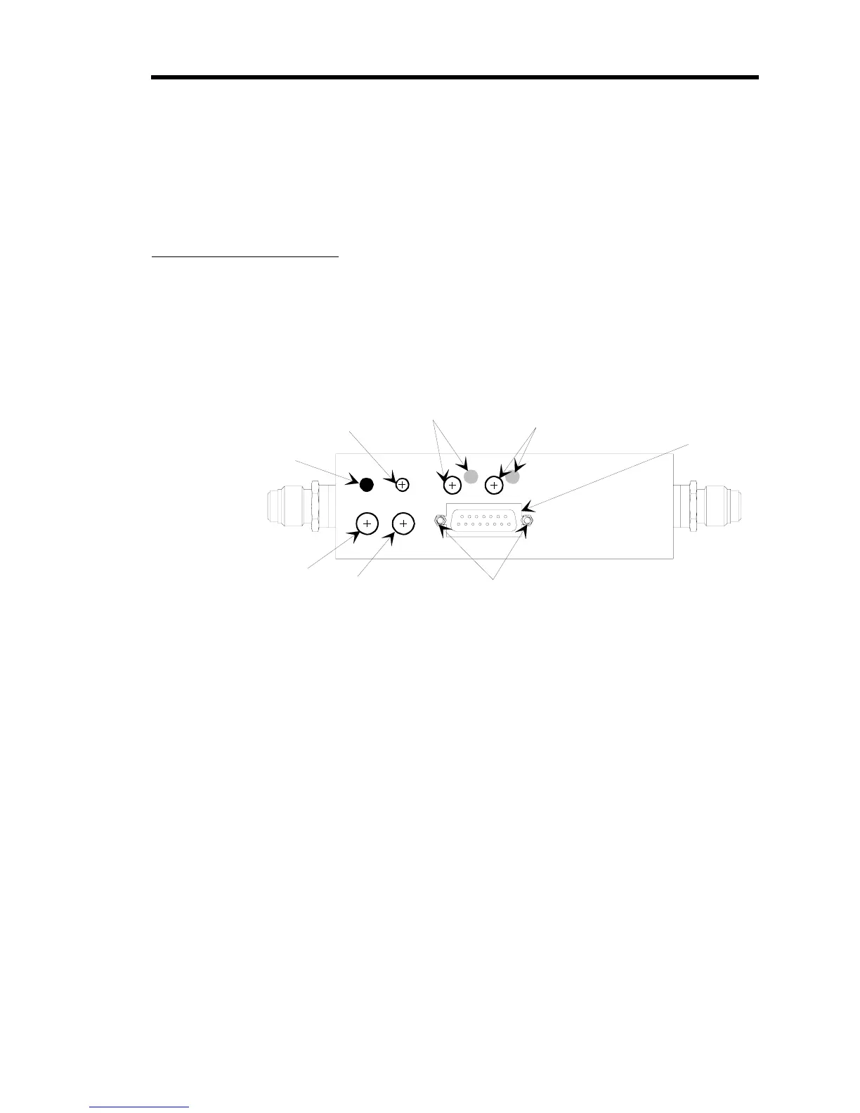
Figure 6 shows the top view of the 649 pressure controller. The user adjustable controls for
pressure zero, pressure span, the P term, the I term, and the trip points are located on the top of
the controller. The trip point settings can be measured through two test jacks, located under the
enclosure, on the Transducer board. Refer to Figure 14, page 39, for the location of the test jacks.
Zero
TPB TPA
Span
I
P
Pr es sur e
I/O Connector
TP A Pot and
Status LED Indicator
TP B Pot and
Status LED Indicator
Pressure Zero Pot
Pressure Span Pot
Proportional
Adjustment
Integral Adjustment
Hex Nuts
Figure 6: Top View of the Type 649 Controller
Pressure Control Range
The 649 controller can control pressure over a range of 5 to 100% of full scale. This means that a
649 controller with a 100 Torr [13.3 kPa] pressure transducer can control pressure from 50 Torr
[6.66 kPa] to 1000 Torr [133 kPa], whereas a unit with a 100 Torr [13.3 kPa] pressure transducer
can control pressure from 5 Torr [666 Pa] to 100 Torr [13.3 kPa].