How To Verify the Orifice Selection
55
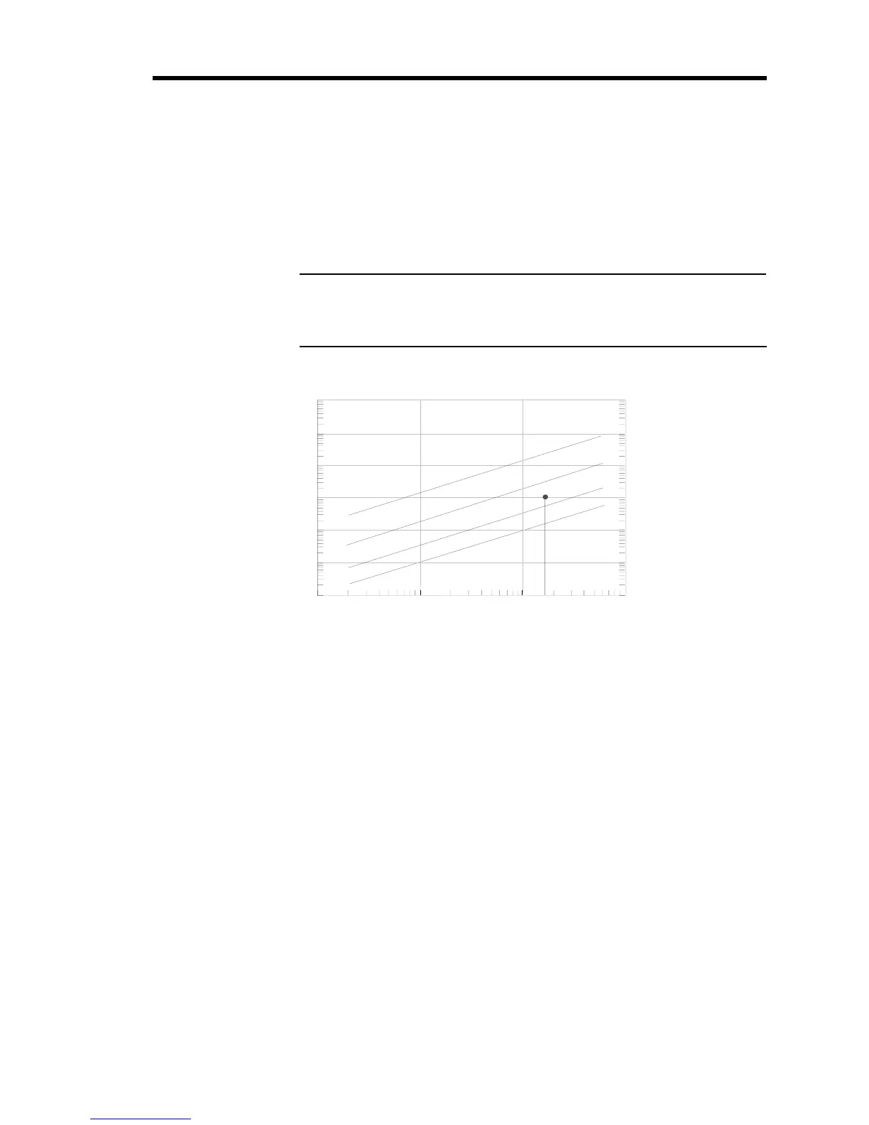
3. Use the index number and your maximum flow rate, to determine the orifice size from
Figure 15.
Each line represents the
maximum flow rate for the orifice. Choose the orifice number
above your point on the graph to ensure that the orifice can deliver the required flow.
Continuing with the example above, the index number is 175, and assuming a maximum
required flow rate of 1000 sccm, the correct orifice would be number 2.
Note
If the point on the graph falls
close to the maximum flow rate for an
orifice, you may choose to use the next largest orifice number.
Index Number
Maximum Flow (sccm)
Maximum Flow (slm)
1
10
100
1000
0.001
0.01
0.1
1
10
100
1000
1
10
100
1000
10000
100000
1000000
3
2
1
A
Figure 15: Flow Range Selection
4. Check the orifice size of your 649 controller (included in the model number).