General Information Chapter Three: Overview
22
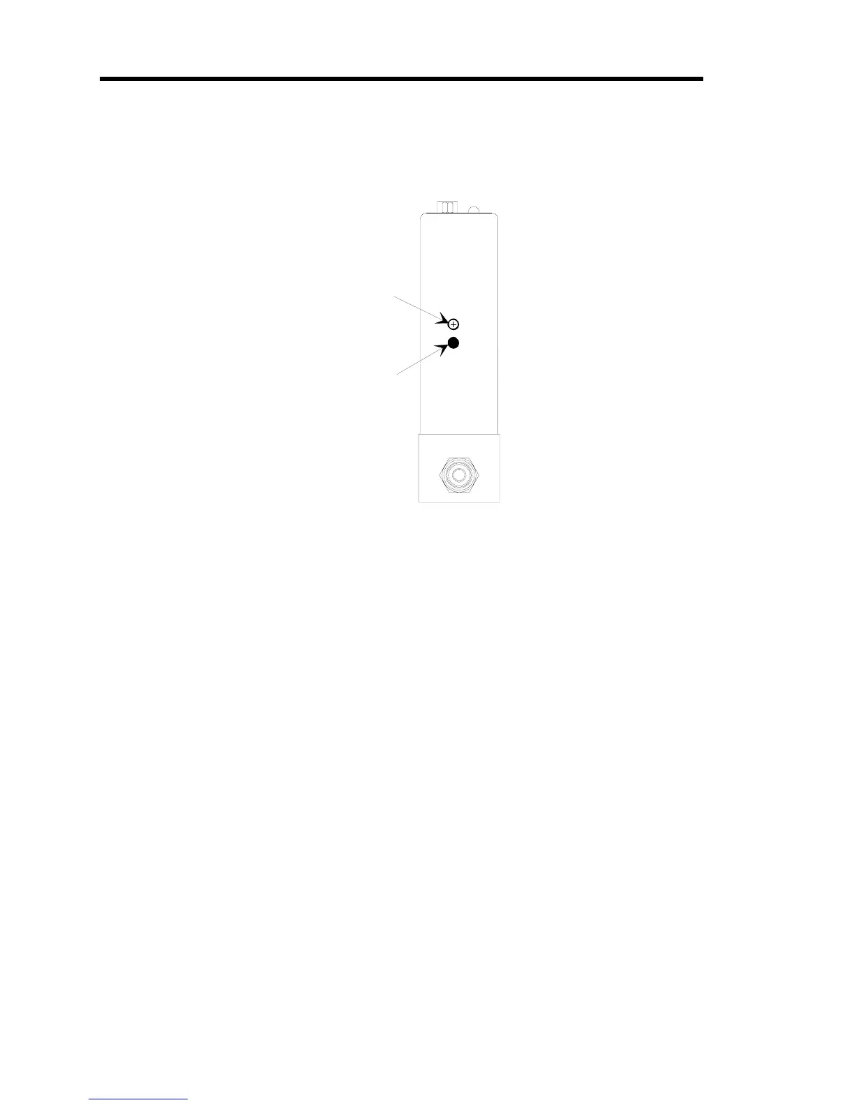
Flow Range
The flow adjustments are located on the inlet side of the controller. The adjustments include the
flow zero and flow span pots.
MFM Adj ust
Span
Zero
Flow Zero Pot
Flow Span Pot
Figure 7: Location of the Mass Flow Meter Adjustments
A Typical Control System
The 649 Pressure Controllers are used in a wide variety of control systems, most of which share
several characteristics. Typically, a control system consists of four basic parts:
• Pressure transducer
• Control electronics
• Control valve
• Pressure system (whose pressure is being controlled)
The 649 Pressure Controller provides the first three components. The pressure transducer is an
MKS Baratron capacitance manometer. The 649 unit contains the electronics necessary for
pressure control. The control valve included in the 649 controller is a proportional control valve.
The pressure system can be any process whose pressure you need to control. In addition, the 649
controller is capable of metering the mass flow of the gas during the pressure control operation.