Electrical Information Chapter Two: Installation
18
Electrical Information
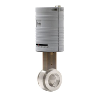
I/O Connector
The 649 controller has one 15-pin, male Type “D” connector that provides the pressure output,
set point input, and trip point output signals. Refer to Figure 6, page 21, for the location of the
connector.
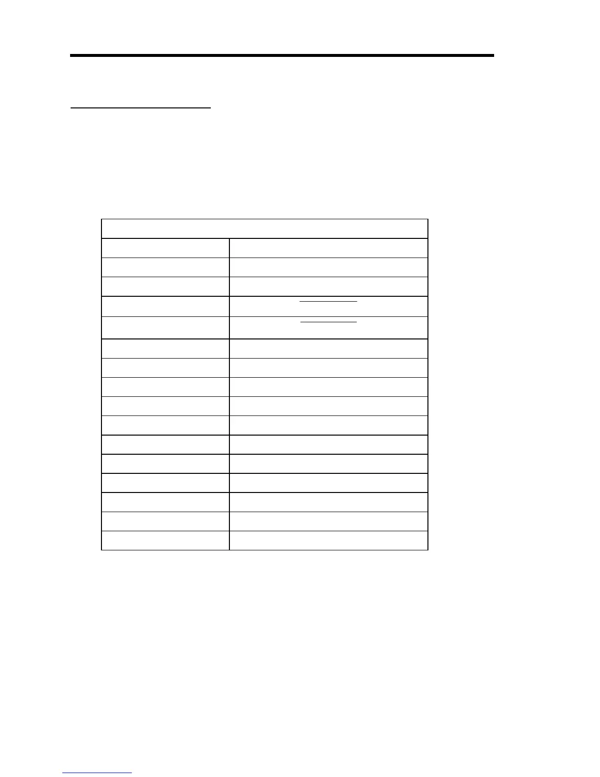
I/O Connector Pinout
Pin Number Assignment
1 Valve Test Point
2 Pressure Signal Out
3
Valve Close
4
Valve Open
5 Power Common
6 -15 VDC Supply
7 +15 VDC Supply
8 Set Point Input
9 Flow Output
10 Optional Input
11 Signal Common
12 Signal Common
13 Trip Point A Out
14 Trip Point B Out
15 Chassis Ground
Table 7: I/O Connector Pinout
Pressure Signal Output (Pin 2)
The 649 controller allows you to access the pressure signal from the pressure transducer, correct
it in some way, and re-introduce it into pin 10 of the I/O connector to be used as the input signal
in closed-loop control. This function is useful if you need to correct for a zero offset.
Pin 2 accesses the pressure signal as it travels from the pressure transducer to the control
circuitry. Pin 10 re-introduces the signal into the 649 controller.