© MOBATIME 12 / 52 800693.16
2.7 Function of the plug connectors
LINES, DC/DCF OUT – JP1 time signal inputs: The DCF/GPS receiver,
polarized impulse line, MOBALine, MOBATIME
serial code, IRIG-B,
power supply output: DC OUT 11–19 V
or passive DCF current loop output
TEMP – JP2 connection of the temperature sensor(s)
CTRL – JP3 connection of the keyboard
RS232 – JP4 (optional) connection of the RS232 serial line
RS485 – JP5 (optional) connection of the RS485 serial line
100 – 240VAC – JP6 powering 100 - 240 VAC voltage
LAN - JP7 (optional) RJ45 10BaseT/100TX (IEEE 802.3)
auto negotiation
PROG – JP8 clock firmware programming
DISP2 – JP20 connection of the second side
RELAY – JP21(optional) switching contact (except DC.57.4)
2.8 Setting elements
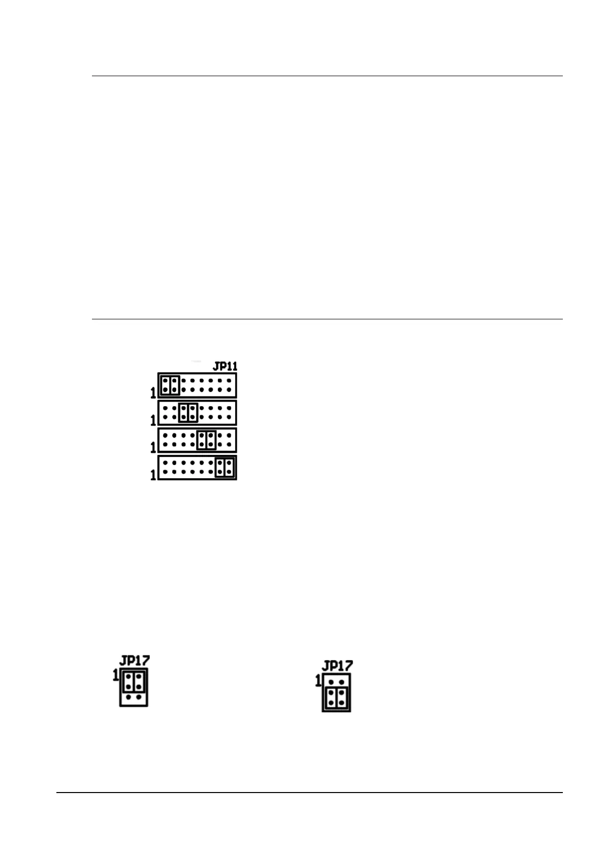
Line type jumper – JP11 for the setting of the slave line type
IRIG / AFNOR
DCF
MOBALine
(Un)polarized impulse line
MOBATIME serial code
PB1, PB2 control pushbuttons
RESET the RESET button
TRE jumper – JP10 (optional) RS485 terminating resistor enable
BATT jumper – JP12 backup battery connection
ISPE jumper – JP9 invoking the firmware programming mode
DCF LED indication of receiving the DCF signal
STATE LED state indication
POWER LED power indication
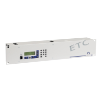
jumper DC Out / DCF Out – JP17 Output signal setting on pins 3, 4
of the JP1 connector
pin3 = DC Out + (11-19V)
DC Out
pin4 = DC Out -
pin3 = (+)
passive DCF Out
pin4 = (-)