© MOBATIME 8 / 52 800693.16
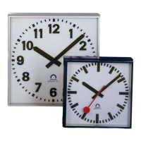
2.2 Double-sided clock
• The double-sided clock consists of two parts, one serving as the control module
(this one encompasses the jacks to connect powering voltage, synchronization
source, the temperature sensor and the keyboard to the clock), and the other
serving as the display module (with the terminal for the connection of the
interconnecting cable). Both clock parts are interconnected via a 10-core flat cable.
The clock suspension part is delivered separately.
• Interlace the incoming conductors through the pipe which serves as the clock
suspension. Secure the ceiling suspension (or the side console) to the ceiling (or
the wall), using 4 wood screws of 5 mm diameter.
• The frame is fixed using two suspensions (at the above) and two sliding springs (at
the bottom). Lift-off both parts of the clock from the anchoring plate using a
screwdriver inserted in between the sheet and the frame at the point where there
are the sliding springs on the clock bottom side (chapter 2.3).
• Disconnect the interconnecting cables by decoupling the terminals on the control
PCB.
• Interlace the incoming conductors through the pipe insert on the anchoring plate,
to the side which finds itself to the opposite of the terminal board. Slip-on the plate
onto the suspension in a way that the screws fit into the upper groove on the pipe
insert. Fix the connection by tightening the screw using an Allen key.
• Interlace the incoming conductors through the opening located next to the terminal
board, and connect the conductors to the terminal board on the anchoring plate, in
accordance with the descriptive nameplate (chapter 2.5). Give an appropriate
shape to the conductors or cut them off at a length which does not obstruct the
mounting of the clock onto the anchoring plate.
• Mount the connectors to the cable of the temperature sensor, to the keyboard
cable, Ethernet cable or the RS 232 and RS 485 interface connectors, if these
have been delivered.
• Place the display part of the clock to the anchoring plate, at a position which is
opposite to the terminal board, and suspend this part onto the upper springs.
Interlace the 10-core interconnecting cable through the lower opening which finds
itself at the closest to the terminal board on the anchoring plate.
• Care should be taken when placing the cables between the frame edge and the
anchoring plate, so as not to nip them. Snap the clock onto the springs by pushing
on the lower frame part.
• Connect the 10-core interconnecting cable and the interconnecting cables into the
corresponding plugs on the clock control PCB.
• Push the temperature sensor connector, the keyboard connector, Ethernet
connector or the RS 232 and RS 485 jacks into the corresponding terminals on the
control PCB (chapter 2.6). Check the marking of the jack-plugs, in order to prevent
their mix-up.
• Put the control part of the clock opposite to the anchoring plate and suspend it
onto the upper springs. Care should be taken when placing the cables between the
frame edge and the anchoring plate, so as not to nip them. Snap the clock in onto
the springs by pushing on the lower part of the frame.
• Check whether the anchoring plate on the sides fits exactly into the grooves
established in both parts of the digital clock (these must be pushed against each
other in a way to mask the anchorage plate (after placing the parts the plate shall
not be seen).
• Remove the blind cap from the opening on the both lower sides of clock.