NICE5000 User Manual 3 Mechanical and Electrical Installation
- 39 -
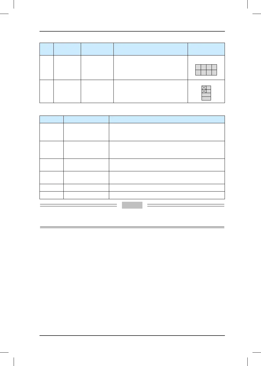
Mark Code Terminal Name Function Description
Terminal
Arrangement
CN5
Y1-M1 to
Y4-M4
Relay output
Normally-open (NO), maximum
current and voltage rating: 5 A, 250
VAC
Function set in F5-32 to F5-35
CN6
CAN2+
CAN2-
Standby
CANbus
communication
terminal
CAN communication for parallel
control
Table 3-3 Description of indicators on the MCB
Mark Terminal Name Function Description
Mod2
Standby
communication
indicator
This indicator blinks (green) when the communication is
normal.
CAN2
Standby
communication
indicator
This indicator is steady on (green) when communication
for parallel/group control is normal, and blinks when the
running in parallel/group mode is normal.
Mod1
HCB communication
indicator
When communication between the MCB and the HCB is
normal, this indicator is on (green).
CAN1
CTB communication
indicator
When communication between the MCB and the CTB is
normal, this indicator is on (green).
X1 to X20 Input signal indicator This indicator is on when the external input is active.
Y1 to Y6 Output signal indicator This indicator is on when the system output is active.
Do not short J6 during normal use. Other jumpers are used for updating programs, and do not
short them if unnecessary.
3.3 CTB Board (MCTC-CTB)
3.3.1 Dimensions and Installation
The car top board (MCTC-CTB) is the elevator car control board of the NICE5000. It
consists of 8 DI terminals, 1 AI terminal, and 9 relay output terminals (standard: 7). It
communicates with the MCTC-CCB and MCTC-HCB through Modbus.
The following figure shows the appearance and structure and installation method of the
CTB.