NICE5000 User Manual 3 Mechanical and Electrical Installation
- 63 -
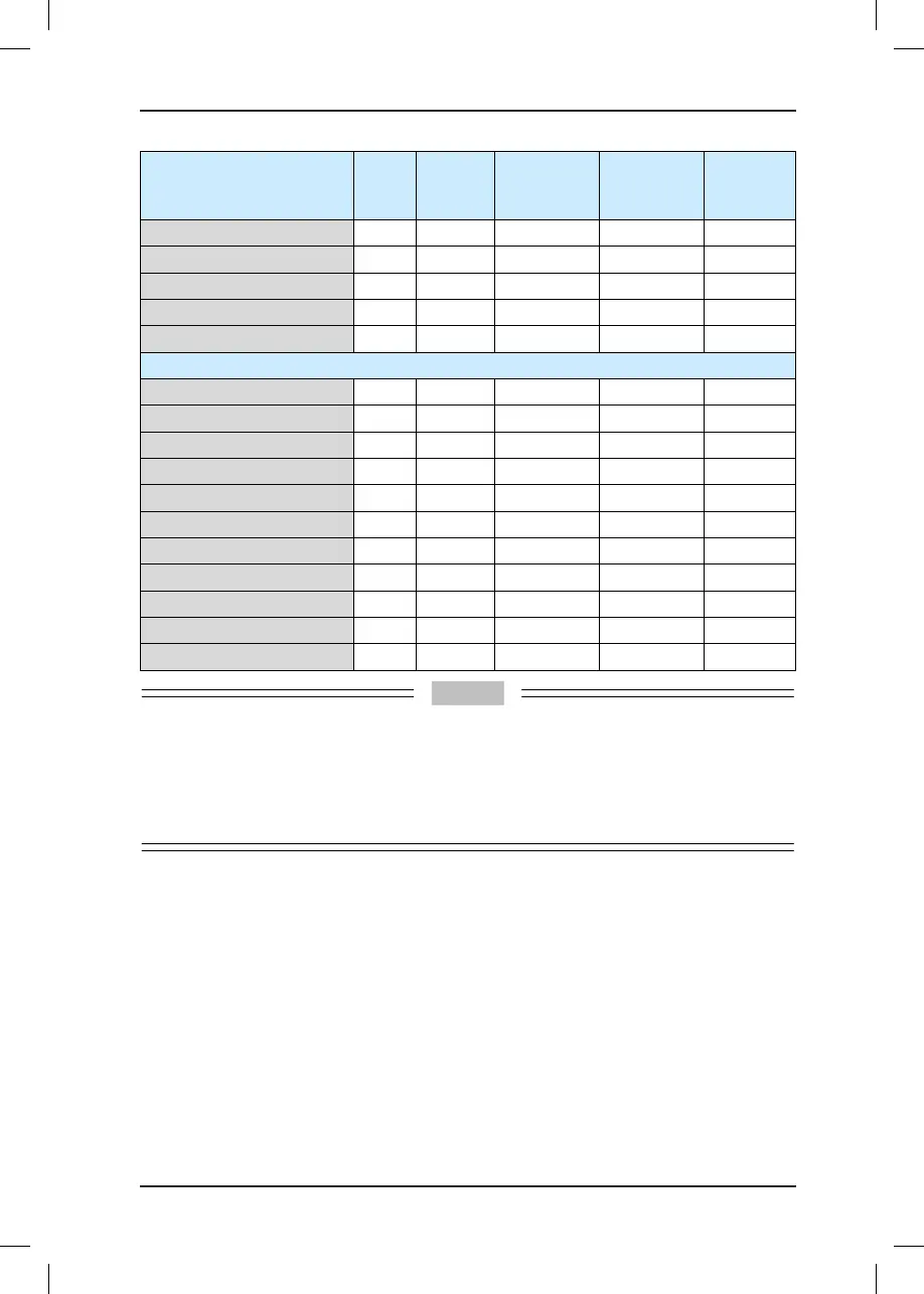
Controller Model
MCCB
(A)
Contactor
(A)
Cable of Main
Circuit (mm²)
Cable of
Control
Circuit (mm²)
Grounding
Cable
(mm²)
220-NICE-LWX-4011-A/B/C0 40 32 6 0.75 6
220-NICE-LWX-4015-A/B/C0 50 38 6 0.75 6
220-NICE-LWX-4018-A/B/C0 63 40 10 0.75 10
220-NICE-LWX-4022-A/B/C0 80 50 10 0.75 10
220-NICE-LWX-4030-A/B/C0 100 65 16 0.75 16
Three-phase 380 V, range: -15% to 20%
NICE-LWX-4002-A/B/C0 10 9 0.75 0.75 0.75
NICE-LWX-4003-A/B/C0 16 12 1.5 0.75 1.5
NICE-LWX-4005-A/B/C0 25 18 2.5 0.75 2.5
NICE-LWX-4007-A/B/C0 32 25 4 0.75 4
NICE-LWX-4011-A/B/C0 40 32 6 0.75 6
NICE-LWX-4015-A/B/C0 50 38 6 0.75 6
NICE-LWX-4018-A/B/C0 63 40 10 0.75 10
NICE-LWX-4022-A/B/C0 80 50 10 0.75 10
NICE-LWX-4030-A/B/C0 100 65 16 0.75 16
NICE-LWX-4037-A/B/C0 100 80 25 0.75 16
NICE-LWX-4045-A/B/C0 160 95 35 0.75 16
To prevent the strong power from interfering with the weak power, the strong-power cables must
be separated from the weak-power cables during cabling in the shaft. Grounding cables must be
used to separate strong-power and weak-power traveling cables. "Strong power" refers to the
voltage of 36 V and above.
The PVC insulation copper lead cable is recommended under 40C ambient temperature in
steady state.
3.9 Electrical Wiring Diagram of the NICE5000 Control System
Figure 3-15 Electrical wiring diagram of the NICE5000 control system
See the last page of this chapter.
3.10 Installation of Shaft Position Signals
In elevator control, to implement landing accurately and running safely, the car position
needs to be identied based on shaft position signals.
These shaft position signals include the leveling switches, up/down slow-down switches, up/
down limit switches, and up/down nal limit switches.
These shaft position signals are directly transmitted by the shaft cables to the MCB of the