3.0 Required Equipment
Description / Requirements
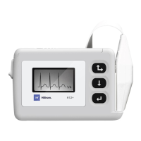
H12+ Modified Battery Compartment
H12+ High Lead Quality Test Fixture
H12+ Low Lead Quality Test Fixture
H12+ Serial number/Date time Compact Flash Card
4.0
Initial Set-up
4.1
Set adjustable power supply to 1.35V ± 0.05V.
4.2
Connect adjustable power supply to H12+ Modified Battery Compartment (TF-0347).
4.3
Set the current switch on TF-0347 to bypass.
5.0
Special Instructions
5.1
While performing all tests, watch for missing or extra segments on the UUT’s LCD.
A missing or extra segment on the LCD indicates afailure.
6.0
Test Procedure
6.1
Low Battery Test
6.1.1
Connect TF-0347 to UUT.
6.1.2
With the power supply set to 1.35V ± 0.05V, verify “no card” is displayed on the LCD.
6.1.3
Turn variable power supply off.
6.1.4
Insert a compact flash card with the latest released H12+ software and no
recorded data on the CF card.
6.1.5
Turn variable power supply on.
6.1.6
Verify “low battery” is displayed on the LCD.
6.1.7
Record result on the TDR.