6.2
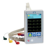
Compact Flash Card Test
6.2.1
Adjust the variable power supply to 1.55V ± 0.05V.
6.2.2
Cycle the power on the power supply.
6.2.3
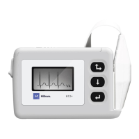
Verify lead check is displayed on the LCD.
6.2.4
Record result on the TDR.
6.3
Real-Time Clock Memory Test
6.3.1
Navigate to the date format setting in the device menu options.
6.3.2
Set the date format to the DD.MM.YYY option and exit the menu.
6.3.3
Cycle the power on the power supply.
6.3.4
Verify the DD.MM.YYYY date format remained.
6.3.5
Record result on the TDR.
6.3.6
Set date format back to MM/DD/YYYY.
6.4
SDRAM / Front End Control Test
6.4.1
With the Serial Number menu option displayed, highlight “end” and press the
button to start the SDRAM test.
6.4.2
Verify the SDRAM test passes.
(Test will indicate pass or fail on LCD. If test passes software indicates pass then
continue to front end control test).
6.4.3
Verify the front end control test passes. (Front end control test takes about 11
seconds to run and will start automatically after a passing the SDRAM test. Test must
be run with all leads open, NO PATIENT INPUT. If front end control test fails, refer to
Appendix A for failurecode explanation.)
6.4.4
Press the button on the UUT to exit self-test.
6.4.5
Record result on the TDR.
6.5
Lead Quality Test
6.5.1
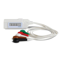
Connect the H12+ High Lead Quality Test Fixture (TF-0345) to the UUT.
6.5.2
Select the lead check menu item on the UUT.
6.5.3
Verify that all of the bars on the LCD are above the horizontal line.
6.5.4
Remove TF-0345 and connect the H12+ Low Lead Quality Test Fixture (TF-0346).