Pin Assignments
http://www.motorola.com/computer/literature B-17
B
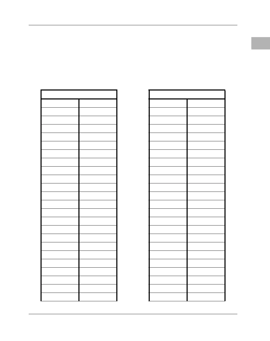
PCI Mezzanine Card Connectors – J21 through J24
Four 64-pin SMT connectors, J21 through J24, supply 32/64-bit PCI
interfaces and P2 I/O between the MVME240x board and an optional
add-on PCI Mezzanine Card (PMC) in PMC Slot 2. The pin assignments
for PMC Slot 2 are listed in the following two tables.
Table B-9. J21 and J22 PMC2 Connector Pin Assignments
J21 J22
1TCK –12V 2 1 +12V TRST# 2
3 GND INTA# 4 3 TMS TDO 4
5 INTB# INTC# 6 5 TDI GND 6
7 PMCPRSNT2# +5V 8 7 GND Not Used 8
9 INTD# Not Used 10 9 Not Used Not Used 10
11 GND Not Used 12 11 Pull-up +3.3V 12
13 CLK GND 14 13 RST# Pull-down 14
15 GND PMCGNT2# 16 15 +3.3V Pull-down 16
17 PMCREQ2# +5V 18 17 Not Used GND 18
19 +5V (Vio) AD31 20 19 AD30 AD29 20
21 AD28 AD27 22 21 GND AD26 22
23 AD25 GND 24 23 AD24 +3.3V 24
25 GND C/BE3# 26 25 IDSEL2 AD23 26
27 AD22 AD21 28 27 +3.3V AD20 28
29 AD19 +5V 30 29 AD18 GND 30
31 +5V (Vio) AD17 32 31 AD16 C/BE2# 32
33 FRAME# GND 34 33 GND Not Used 34
35 GND IRDY# 36 35 TRDY# +3.3V 36
37 DEVSEL# +5V 38 37 GND STOP# 38
39 GND LOCK# 40 39 PERR# GND 40
41 SDONE# SBO# 42 41 +3.3V SERR# 42
43 PAR GND 44 43 C/BE1# GND 44
45 +5V AD15 46 45 AD14 AD13 46
47 AD12 AD11 48 47 GND AD10 48

 Loading...


