6 Installation
Messko GmbH 2020 41BA4001150/10 EN MSENSE
®
DGA 2/3
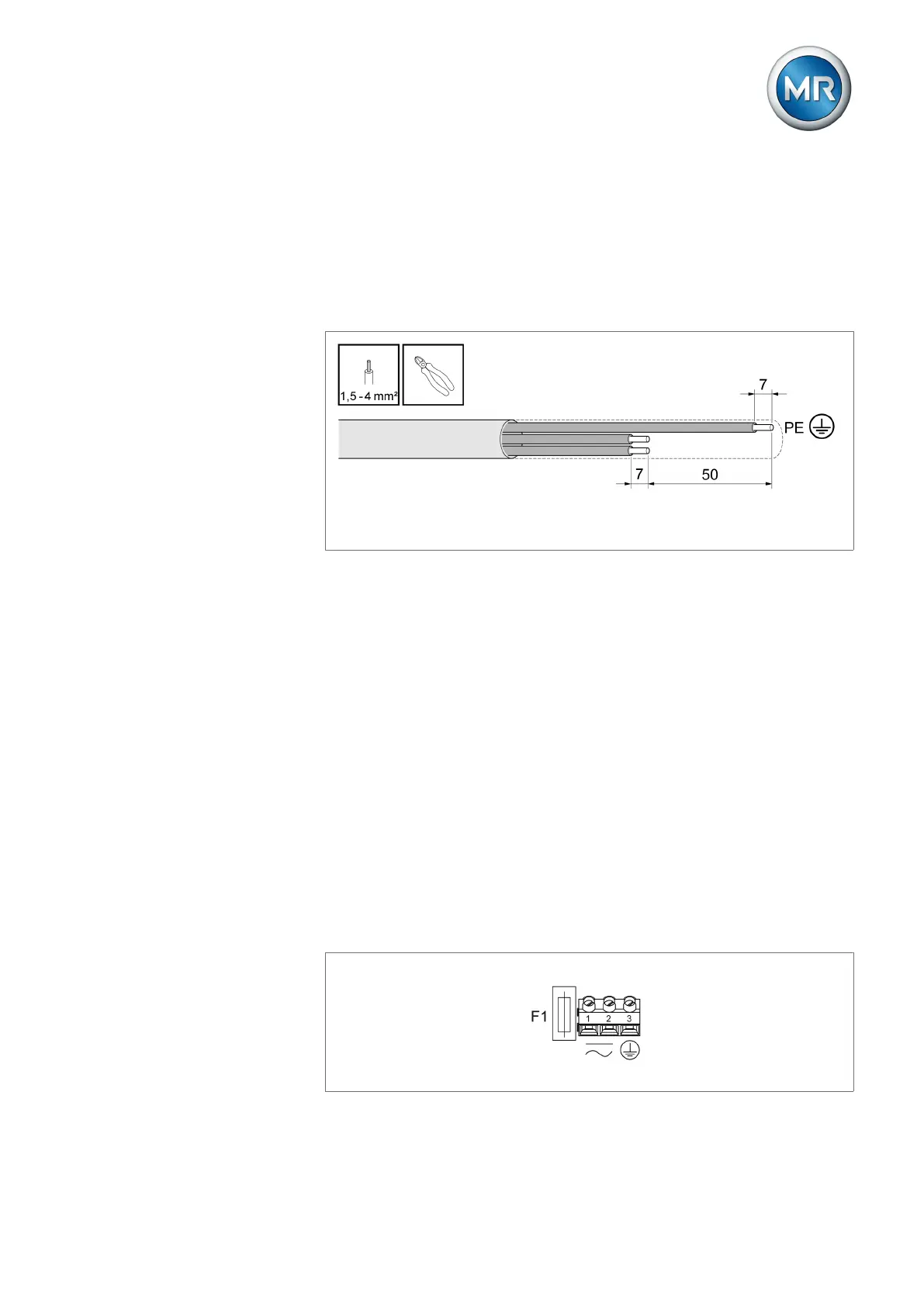
To prepare the cable correctly, proceed as follows:
1. Open the device connection area. To do so, unscrew the 4 captive screws
on the housing cover. The cover is connected to the device via hinges and
can be flipped open.
2. Remove the supply voltage cable jacket and cut the cable such that the
length of the PE wire is 50mm longer than the wires for L and N. Strip
7mm (1/4") of the insulation from the wires and cap them off with ferrules.
Figure27: Preparing the cable
3. Remove the jacket from the cable for the relay and analog outputs. Strip
off 7 mm (1/4“) of insulation from the wires and cap them off with ferrules.
4. Unscrew the required cable screw connections (M20x1.5).
5. Insert a sufficient length of cable through the cable connection and rubber
gasket and tighten the cable connection such that moisture cannot pene-
trate into the connection area from outside.
6. Insert locking screws into the unused cable connections or replace the en-
tire cable connection with a locking screw such that the pass-through is
watertight.
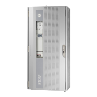
6.3.4 Supply voltage and protective conductor
In order to connect the cable for the supply voltage and the protective con-
ductor, proceed as follows:
1. Insert wire for the protective conductor into terminal 3 (PE) and tighten the
screw terminal to 0.5Nm.
2. Insert wires for the supply voltage into terminal 1 and terminal 2 and
tighten the screw terminals to 0.5Nm.
Figure28: Supply voltage and protective ground connection