14 Appendix
Messko GmbH 2020 97BA4001150/10 EN MSENSE
®
DGA 2/3
14.4 Electrical connection
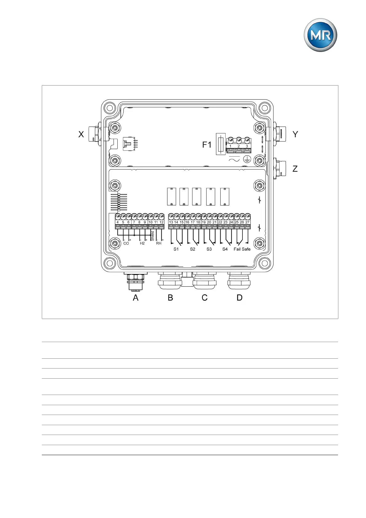
Figure76: Electrical connection
1-2 Supply voltage (overvoltage category III)
95...280 V AC 50/60 Hz or 95...280 V DC (any polarity)
3 Protective conductor
4-12 Analog outputs 4…20mA passive (must be supplied with 24 V DC)
13-27 Main switching contacts (crossovers for state signaling): capacity: 30 V DC / 5 A to 300 V DC / 0.25 A or 250
V AC / 5 A; max. 400 V AC, cos φ = 1 at 85°C, observe warning information [►Section 6.3.7, Page 44].
F1 Safety fuse 500 V, 500 mA, delayed-action
A M12 socket, type A fro Modbus RTU (RS485) and for USB service adapter (included in delivery)
B M20x1.5 cable screw connection for analog outputs
C M20x1.5 cable screw connection for signaling relay
D M20x1.5 cable screw connection for supply voltage
X, Y, Z Vents