6 Installation
Messko GmbH 2020 45BA4001150/10 EN MSENSE
®
DGA 2/3
To connect the system periphery cables to the main switching contacts, pro-
ceed as follows:
ü Only use specified cables. Note the cable recommendation.
1. Connect the leads that are to be wired to the device in accordance with
the illustration of the main switching contacts. When doing so, also ob-
serve the illustration "Electrical connection" [►Section 14.4, Page 97] in
the appendix.
2. Tighten all screw connections to a maximum of 0.5Nm.
6.3.8 SCADA connection
6.3.8.1 Standard interface Modbus RTU
The device can be connected with a SCADA system via the Modbus inter-
face. This is designed as a 4-conductor system [►Section 6.3.8.4, Page
46], but can also be integrated into a 2-conductor system [►Section
6.3.8.5, Page 47].
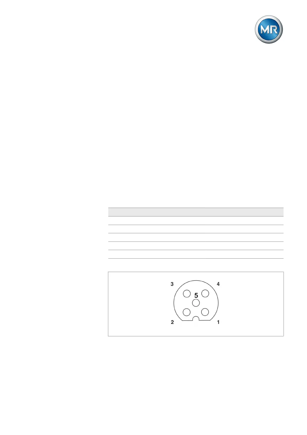
The following signals are available in the 4-conductor system via the M12
socket:
M12 socket / Modbus (RTU) interface assignment
PIN 4-conductor system 2-conductor system
1 TXD0 / TX+ / Y D0 / D+ / A
2 TXD1 / TX- / Z D1 / D- / B
3 RXD1 / RX- / B D1 / D- / B
4 RXD0 / RX+ / A D0 / D+ / A
5 Common Common
Figure32: Integrated device socket (schematic)
6.3.8.2 Setting the Modbus RTU transmission speed
You can configure the following settings for the Modbus RTU interface using
the MESSKO® MSET parameterization software: