6 Installation
Messko GmbH 202044 BA4001150/10 ENMSENSE
®
DGA 2/3
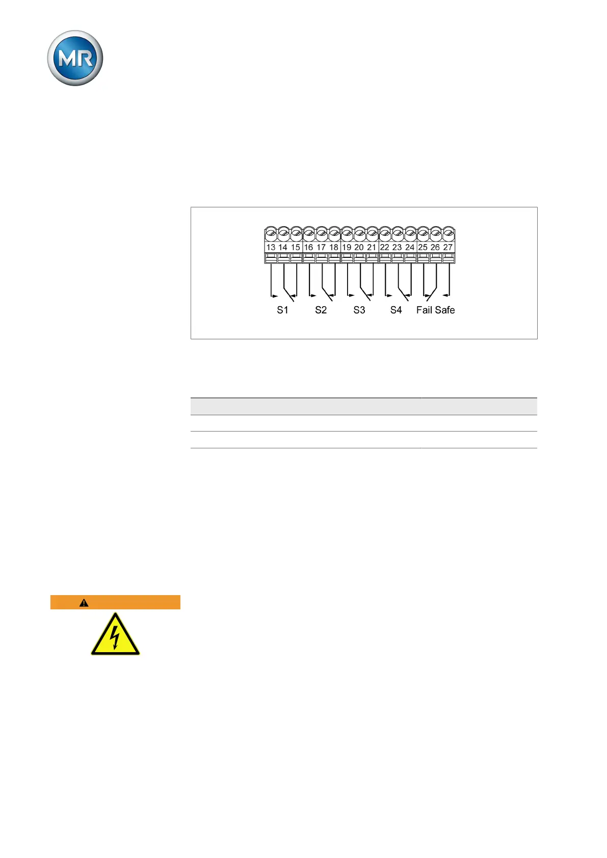
6.3.7 Main switching contacts
The device has 5 floating main switching contacts: S1, S2, S3, S4 and one
safety switching contact = fail-safe relay (FSR) for status signaling. The con-
tactors are designed as changeovers and are connected to the terminals
13/14/15 (S1), 16/17/18 (S2), 19/20/21 (S3), 22/23/24 (S4) and 25/26/27
(FSR).
Figure31: Main switching contacts
The main switching contacts are shown in the idle state in the figure. Using
the fail-safe relay as an example, this means:
Status Contact 25-26 Contact 26-27
Idle state Closed Open
Fault Open Closed
The contact current capacity is max. 5A / 250AC or 5A / 30VDC.
S1…S4:
The assignment can be configured via the MESSKO® MSET parameteriza-
tion software. The relay triggers when the configured threshold value is ex-
ceeded.
FSR:
The fail-safe relay serves as a safety contact for signaling errors in the event
of a voltage failure or an internal device error.
WARNING
Electric shock!
When a dangerous electrical voltage is applied to one of the main switching
contacts S1, S2, S3, S4 or the fail-safe relay, the neighboring main switch-
ing contacts may not be operated with safety extra-low voltage.
► Operate all main switching contacts uniformly, either with safety extra-low
voltage only or with higher voltages only.
► Also observe the specifications in the chapter "Technical data" [►Section
13, Page 90].