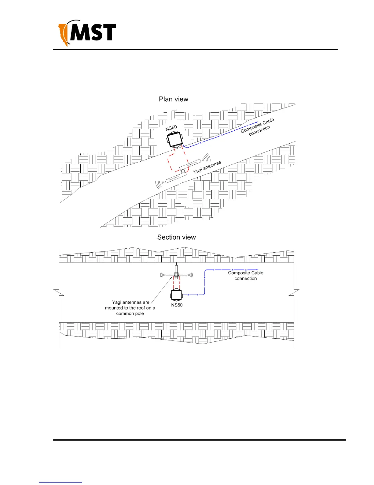
Each antenna is connected to a separate WAC in the NS50, or a Wi-Fi signal splitter can be used
to split the signal from one WAC in two directions.
The network switch is cable tied to the rock mesh and connected to the composite cable that
provides power and network connectivity.
Figure 9: Installation scheme in a straight drive
3.3.3 Installation in a Stope
A curved decline / incline installation scheme is shown in Figure 10: Installation cheme in a curved
decline/incline.
A Yagi antenna is positioned at the end of the curve for directional wireless coverage.
The Yagi antenna is clamped to a mounting pole, and is chemically adhered into the mine roof.
A panel antenna is roof mounted in the middle of the curve providing wide wireless coverage.
Each antenna is connected to a WAC in the NS50.
 Loading...