44
Temposonics
®
R-Series SSI
Operation Manual
Temposonics
®
R-Series SSI
Operation Manual
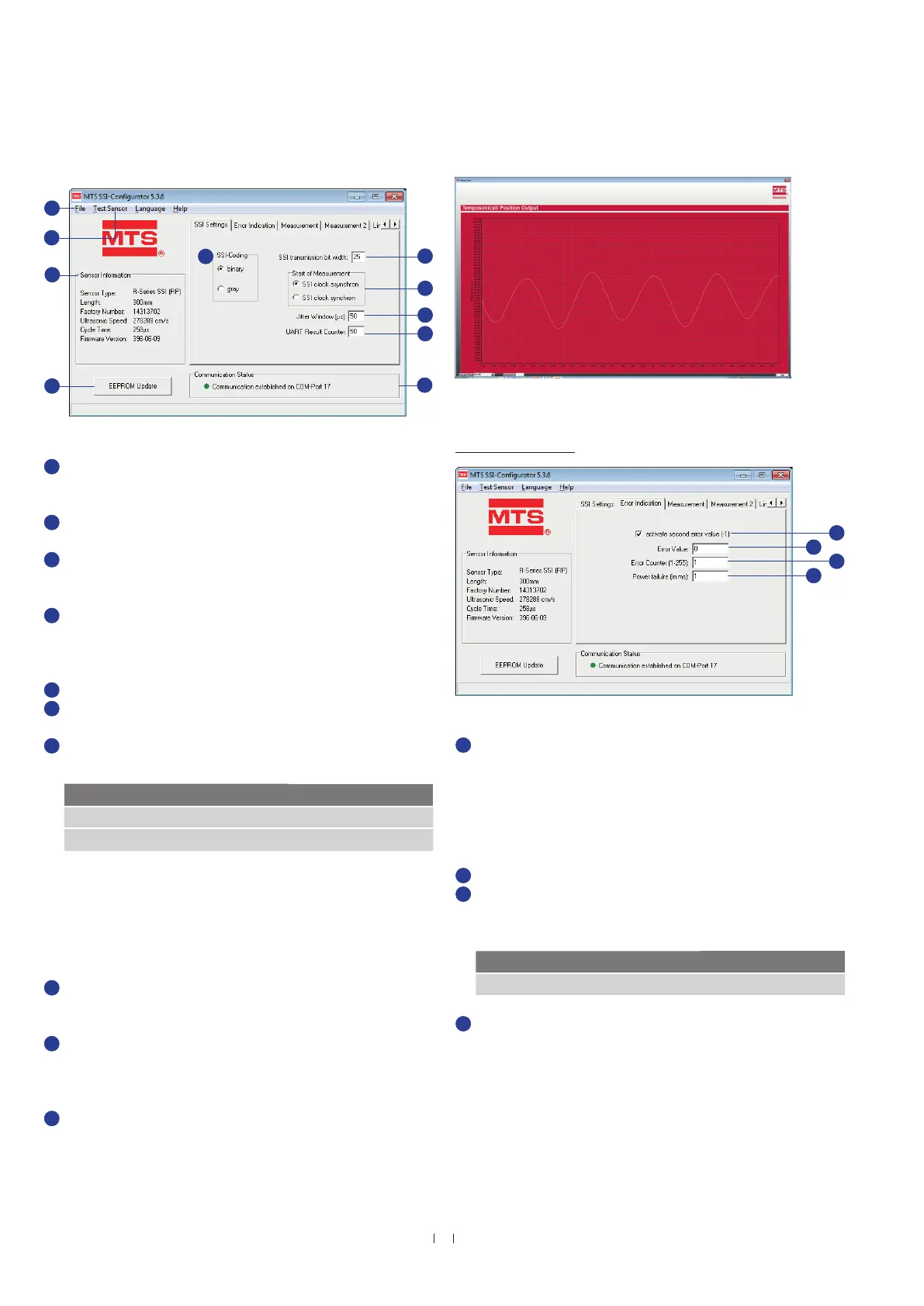
Fig. 57: MTS SSI-Configurator, SSI Settings
Fig. 58: Graphical display of position values via Test Sensor
Fig. 59: MTS SSI-Configurator, Error Indication
1
In the File menu, you can save the sensor configuration on
hard disk, print it out or load it into the sensor. Moreover, this
menu permits returning to the factory setting.
2
Via Test Sensor the position of the magnet is displayed graphically.
(Fig. 58).
3
Frame Sensor Information contains the invariable sensor
parameters, which are read in automatically when connecting the
sensor.
4
Click on EEPROM Update to send and store altered parameters
(highlighted with a blue background) permanently in the sensor.
Subsequently, the stored values are displayed again with a white
background.
5
Use the option box binary or gray to determine the SSI coding.
6
In this field you can set the SSI transmission bit width for the
position output.
7
Use the option box SSI clock asynchron and SSI clock synchron
to change the start of measurement.
In asynchronous mode the sensor starts measuring and provides
the position independent of the PLC.
In synchronous mode 1 the output of the position of the
Temposonics
®
SSI sensor is matched to the data request
cycle of the controller. The contouring error complies with the cycle
time of the stroke length.
8
The jitter specifies the time interval between the start of measuring
and the SSI clock, which is given by the PLC (for “SSI clock
synchron”).
9
Via
UART Result Counter you define a time interval for the function
Test Sensor to send a position value Fig. 58 (graphical presentation
of position values).
Example: If you choose “50” in the field UART
Result Counter, each 50. measurement will be displayed.
10
Communication Status indicates that the sensor is connected
successfully.
11
If the check box activate second error value (-1) is active, an error
value of “−1” is output if the sensor is used with more magnets as
specified before. If the check box is not active and the sensor is
used with more magnets as specified before, the value which was
defined in field Error Value will be displayed. The Error Value will
also display if the sensor is used with less magnets as determined
before.
12
In the case of failure the sensor transmits the Error Value.
13
Use the field Error Counter to determine how often in the case of
failure (1…255 times) the old measurement value will be repeated,
before the Error Value will be displayed.
14
In this field you can define a period (1…100 ms), during which the
power supply of the sensor can be fallen short of, without the Error
Value to display. Set the value to “0” to deactivate the function
Power failure (in ms).
MTS SSI-Configurator user interface
MTS SSI-Configurator R-Series order code
Error counter complies with Error delay
10
6
MTS SSI-Configurator R-Series order code
SSI clock asynchron complies with Asynchronous mode
SSI clock synchron complies with Synchronous mode 1
2
5
8
9
7
Tab “Error Indication”
11
12
13
14
1
3
4

 Loading...