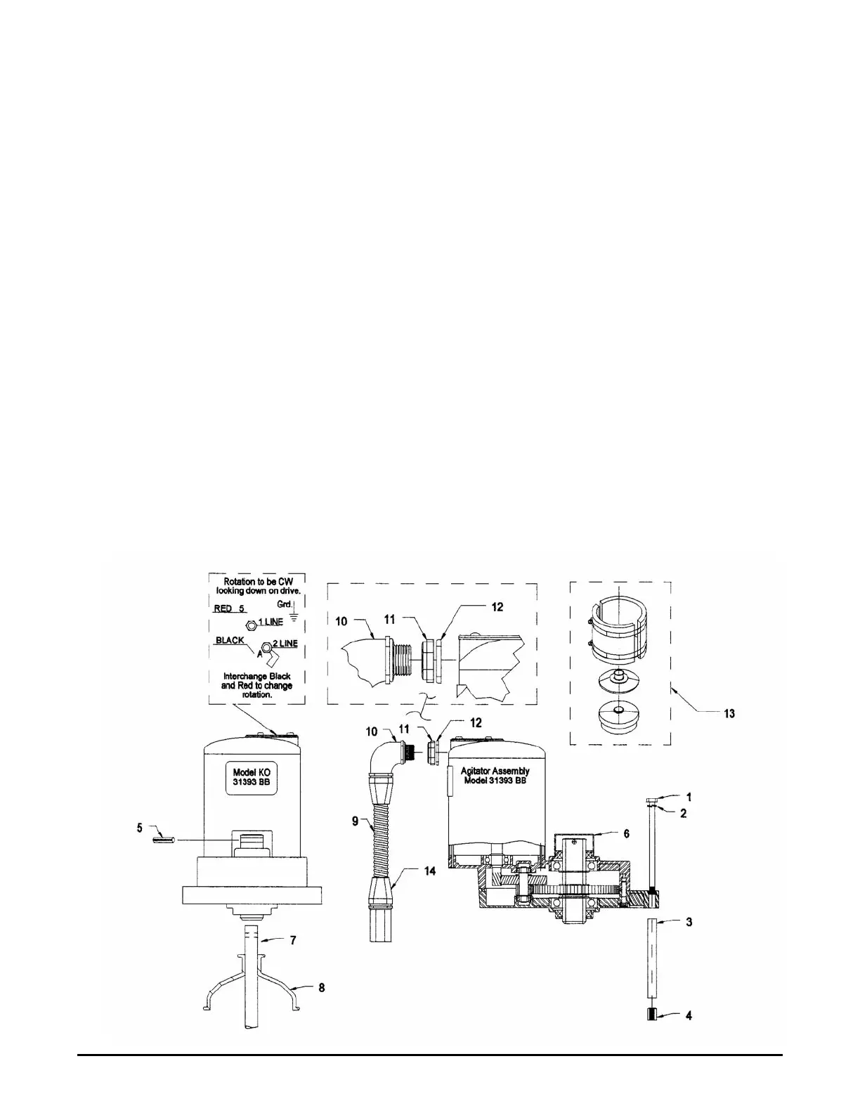
2.11 Agitator Assembly Installation
1. Remove the protective plastic shipping wrap and position the agitator shaft (Item 7) up through
the opening in the top of the milk cooler. Slip the neoprene shield (Item 8) over the end of the
agitator shaft. Be careful not to damage the internal and external finishes of the cooler during this
procedure.
2. Position the spacer sleeves (Item 3) on the studs located on the top of the cooler. Apply Never-
Seez
®
to the shaft end (Item 7) and threads of the cap screws (Item 1). Slip the agitator shaft
through the agitator drive and secure in place with cap screws (Item 1), lock washers (Item 2), and
spacer sleeves (Item 3).
3. Align the hole in the agitator shaft with the hole in the output shaft of the agitator drive and insert
the roll-pin (Item 5).
4. Place the blue plastic cap (Item 6) over the top of the output shaft after assembly.
5. Thread the 90° liquid-tight conduit fitting (Item 10) through the plastic nut (Item 11) with the flat-
washer flange facing the motor. Slip the cut gasket (Item 12) over the threads and thread the
assembly into the agitator motor. Insert the 3-wire cable through the straight conduit fitting,
conduit, and 90° fitting installed in the motor. Thread the straight liquid-tight conduit fitting into
the full coupling attached to the milk cooler. Connect L1 and L2 as shown in the wiring schematic,
secure the ground wire under the grounding screw in the motor housing. Ensure clockwise
rotation as viewed from the top of the drive.
6. The optional agitator weather shield (Item 13) must be installed on all agitators that are located
exterior of the milk room.
Figure 8 - Agitator Installation
Sentry II with Auto-Dosing Assembly Operating Instructions 9 Effective April 1, 2000