4.3 Sentry II Thermocouple Sensor Wiring
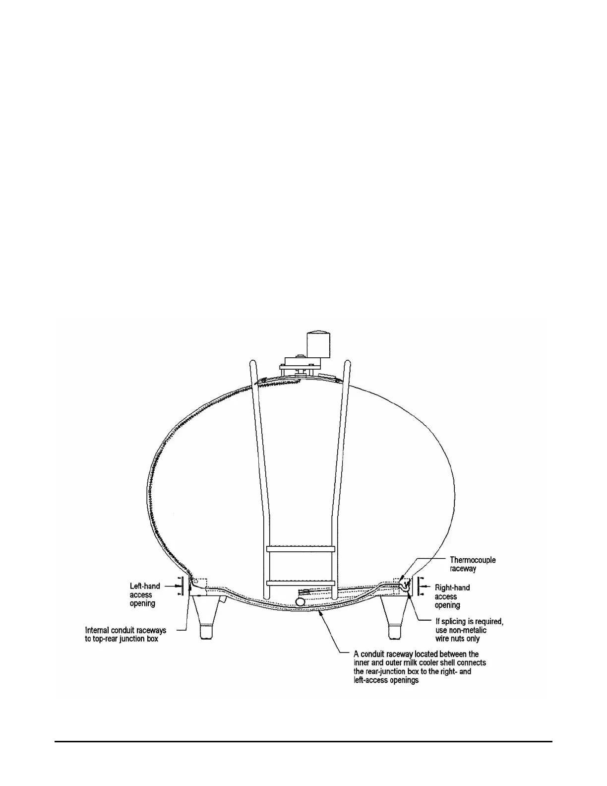
1. Route the thermocouple cable from the right-hand access opening through the internal conduit to
the left-hand access opening in the milk cooler.
2. Route the thermocouple cable from the left-hand access opening through the internal conduit to
the top-rear junction box of the milk cooler.
3. Mating copper (+) to copper (+) and constantan (-) to constantan (-), splice the thermocouple
cable to the thermocouple extension cable in the top-rear junction box of the milk cooler with
non-metallic wire nuts. See “Important Thermocouple Splicing Information” in Section 4.4.
4. Cut and insulate the foil shield and drain wire of the thermocouple extension cable at the top-rear
junction box. The drain wire should be grounded (one end only) at the Sentry II control cabinet.
5. Route the thermocouple extension cable from the rear junction box to the wall-mounted Sentry II.
Avoid routing this cable in conduit that contains high-voltage conductors.
6. Connect the copper (+) thermocouple conductor to Terminal No. 11 and the constantan/silver (-)
to Terminal No. 10 of the temperature control. Connect the drain wire to the electrical ground in
the Sentry II enclosure. See Figure 27.
Figure 26 - Sentry II Thermocouple Sensor Wiring
Sentry II with Auto-Dosing Assembly Operating Instructions 26 Effective April 1, 2000