3.2 PLC Electrical Troubleshooting (Input and Output Data)
The LED lights on the top cover of the PLC provide a quick and simple visual aid for troubleshooting
the inputs and outputs. Compare the PLC input and output terminology from Table 1 with the
illuminated LED lights on the PLC for accurate troubleshooting of each individual circuit. Figure 23
provides an exploded view of the PLC electrical connections.
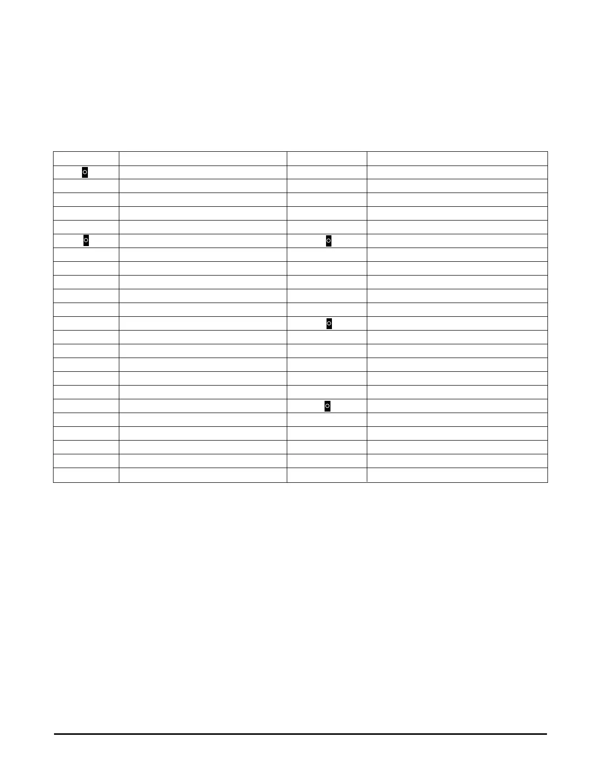
Table 1 - PLC Inputs and Outputs
Service Note: Inputs “X” are 24 VDC, outputs “Y0 - Y11” are 24 VAC, and “Y12 - Y15” are 240 VAC.
Sentry II with Auto-Dosing Assembly Operating Instructions 22 Effective April 1, 2000
Inputs Input Description Outputs Output Description
Not Used 24V 24 VDC (+) Output
L (Line) L1 of 240 VAC Supply OV 24 VDC (-) Output
Ground Electrical Ground COM0 (24VAC) Power for Y0, Y1, and COM1
N L2 of 240 VAC Supply Y0 (24VAC) Condensing Unit 1 (or) Hot Solenoid
S/S 24 VDC (-) Y1 (24VAC) Condensing Unit 2 (or) Cold Solenoid
Not Used Not Used
S/S 24 VDC (-) COM1 (24VAC) 24V Power for Y2-Y5 and COM2
X0 Agitator Sampling Switch Y2 (24VAC) Alarm Lamp
X1 Pre-Start Agitator Switch Y3 (24VAC) Agitator Lamp
X2 Pre-Start Cooling Switch Y4 (24VAC) Pre-Start Agitator Lamp
X3 Cooling Bottom Unit Switch Y5 (24VAC) Pre-Start Cooling Lamp
X4 Cooling All Units Switch Not Used
X5 Wash Cycle Start Switch COM2 (24VAC) 24V Power for Y6-Y11
X6 Acid Cycle Start Switch Y6 (24VAC) Cooling Bottom Unit Lamp (or) Drain Valve
X7 Sanitize Cycle Start Switch Y7 (24VAC) Cooling All Units Lamp (or) Detergent Wash
X10 Cooling Selector Switch Y10 (24VAC) Acid Cycle Lamp
X11 Wash Selector Switch Y11 (24VAC) Sanitize Cycle Lamp
X12 Temperature Control Set Point Not Used
X13 High/Low Temp. Alarm Input COM3 (240VAC) L1 of 240VAC/Power for Y12-Y15
X14 Not Used Y12 (240VAC) Agitator Coil (or) Wash Pump Coil
X15 Water Level Pressure Switch Y13 (240VAC) Detergent Chemical Pump
X16 Not Used Y14 (240VAC) Acid Chemical Pump
X17 Not Used Y15 (240VAC) Sanitize Chemical Pump