A. GENERAL
This section provides the recommended procedures for properly
installing the 750 Series II Conductivity/Resistivity Monitor/
controller, and sensors. For OEM models see section C.
WARNING: THE MYRON L
®
COMPANY RECOMMENDS THAT
ALL MOUNTING AND ELECTRICAL INSTALLATIONS BE
PERFORMED BY QUALIFIED PERSONNEL ONLY. FAILURE
TO DO SO COULD CAUSE DAMAGE TO INSTRUMENT, AND
COULD BE HARMFUL OR FATAL TO PERSONNEL.
B. MECHANICAL INSTALLATION
All Monitor electronics are packaged inside drip/weather-proof
housings. The physical dimensions of the housing is suitable for
panel, bench or surface mounting.
There are four basic guidelines to consider when selecting a
Monitor’smountinglocation:
1. SelectasitethatlimitstheMonitor’sexposureto
excessive moisture and corrosive fumes.
2. For best results, position your Monitor/controller and
sensor as close as possible to the point(s) being
controlled. The 750 Series II Conductivity/TDS &
Resistivity Monitor/controllers are not designed to
operate with a Sensor cable length that exceeds 100 ft./
30 meters.
3. If at all possible, mount the Monitor at eye level for
viewing convenience.
4. If needed, the enclosure may be rotated or mounted
upside down so that the cutouts are on the opposite
side.
1. SURFACE MOUNTING WITH SMP
NOTE: A Surface Mounting Plate (SMP50) may be required
when access to the back side of the mounting site is impractical
or if the Monitor/controller must be mounted on a solid wall. The
SMP50 comes with the proper hardware to mount the Monitor/
controller to the SMP, however, the installer must provide the
four (4) additional screws/bolts to mount the SMP to the wall or
xture.Theirsizeistobedeterminedbytheuser.
1. Select your mounting location. Mark and drill the four
(4) required mounting holes. For hole locations, use the
SMP as a template.
2. Drill the corner holes in the SMP according to the size
of the screws or bolts selected.
3. Attach and securely fasten the SMP to the Monitor
using the 1/4” X 20 X 3/8” screws provided.
4. Mount the SMP to the prepared site using the selected
screws or bolts.
2. SURFACE MOUNTING WITHOUT SMP
NOTE: Surface mounting will require two (2) 1/4 “ X 20 screws
of a length equal to the thickness of the mounting site plus 3/8”
1. Select mounting site location. Mark and drill the
required mounting holes. For hole drilling locations, see
gureII.B.1.
2. Insert the 1/4” X 20 screws into the holes from the side
opposite the mounting site.
3. Hold the Monitor in place while starting and tightening
the mounting screws.
3. PANEL MOUNTING
A panel mounting fastening kit is provided with all Monitor/
controllers. Panel mounting will require the use of the fastening
kit’stwo(2)4-40mountingscrews/nutsortwo(2)#4x1/2”
sheetmetalscrews.SeegureII.B.1.forpanelcutout
dimensions.
1. Select your mounting location. Mark the appropriate
panel cutout and complete the necessary panel cut.
2. CarefullyunfastenandseparatetheMonitor’sfront
panel from its enclosure.
3. Disconnectallpanelcable(s)/wire(s)fromtheMonitor’s
Control board.
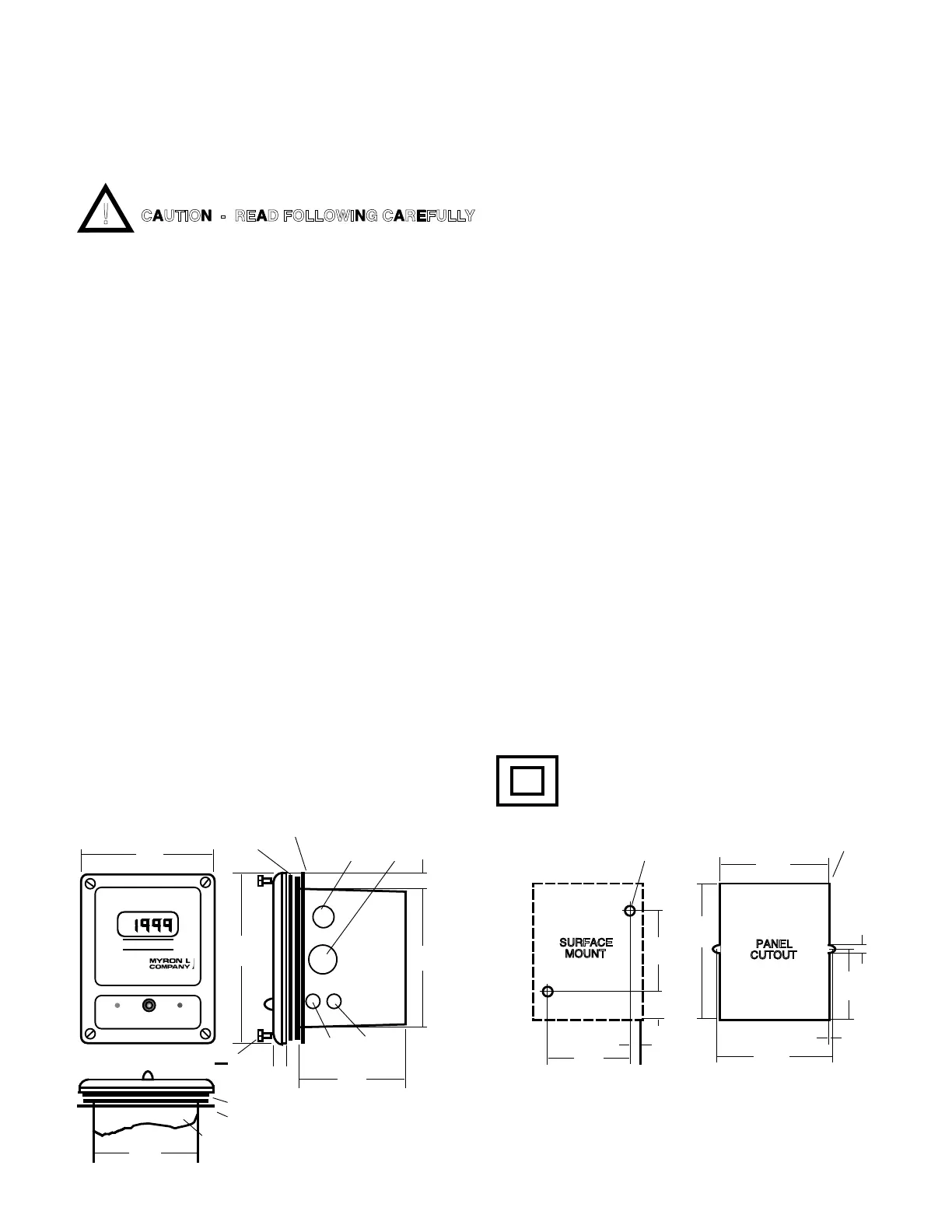
NOT TO SCALE
DIMENSIONS IN INCHES
(MILLIMETERS)
3.10
(79)
0.40
(10)
SURFACE
MOUNT
1.05
(27)
2.84
(72)
0.31 DIA, X2
(8)
5.00
(127)
3.96
(101)
0.13 RAD MAX, X
(3)
0.113
(3)
2.54
(64)
4.17
(106)
0.11
(3)
PANEL
CUTOUT
HIGHLOW
SET POINT
4.80
(122)
3.89
(16)
0.88 DIA
(22)
1.13 DIA
(29)
3.78
(96)
750
MICROSIEMENS / CM
II
6-32x3/8" x4
Face Plate Gasket
Face Plate Gasket
Panel Gasket
0.63 THK
II. INSTALLATION
9
SURFACE AND PANEL MOUNTING DIAGRAMS
Figure II.B.1
CAUTION - READ FOLLOWING CAREFULLY

 Loading...