4. Slide the enclosure through the panel cutout
untilitsangecontactsthepanel.
5. Insertmountingscrewsthroughtheange
mounting holes and tightly secure.
6. Reconnect all panel cable(s)/wire(s) and re-
secure the front panel using 6-32 x 3/8”
screws provided.
Caution: Do not use 6-32 x 1/2” used on “picture
frame” front panel models.
C. OEM MECHANICAL INSTALLATION
This section provides the recommended procedures for properly
installing the OEM 750 Series II Conductivity/Resistivity Monitor/
controller.
NOTE: Mounting of the OEM monitor/controller circuit board
is left up to the OEM. It is recommended that the following be
noted and observed.
1. CIRCUIT BOARD
Total height of CB is 1.40” (36mm).
The circuit board has four (4) .175” (4.4 mm) holes for mount-
ing. The centers are 3.10” (78.7 mm) x 4.10” (104.1 mm) see
gureII.C.1.CBmustbemountedonatleast.250”(6.35mm)
standoffs to prevent shorting to metal chassis (standoffs user
supplied). CB must be mounted in a clean and dry environment.
Allow working room for inserting wires, testing and calibration.
Indicator lights and switches require 1/4” (6.35mm) holes.
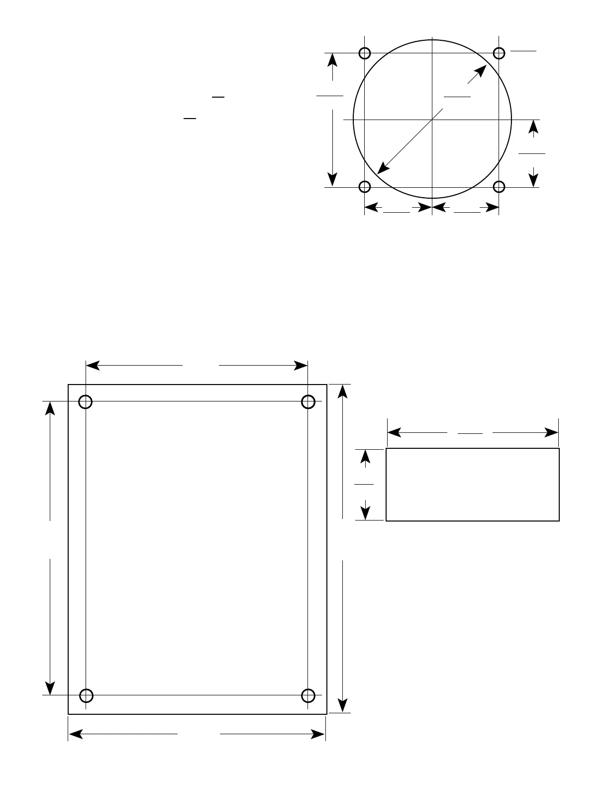
2. METER MOVEMENT
RefertogureII.C.2fordimensions.
1. Cut opening in user panel.
2. Drill four (4) holes at locations as shown.
3. Install meter movement using supplied
hardware.
4.585
3.600
4.100
(78.74)
Figure 11.C.1
10
2.218 Dia.
.940
1.880
.940
.940
(23.88)
(3.125)
56.34
Analog Meter Hole Pattern
Figure II.C.2
2.390
(60.71)
.980
DIGITAL DISPLAY CUTOUT
PATTERN
Figure II.C.3
3. DIGITAL DISPLAY
RefertogureII.C.3fordimensions.
1. Cut opening in user panel
2. Install LCD with brackets
supplied.

 Loading...