28
5. Set front panel down or carefully allow to hang from the
harness. Do not drop as the harness connector will pull
out allowing the front panel to fall.
6. While holding the display and the plastic display
retainer plate, carefully remove the display harness
connector. Do not drop the display.
7. Remove and discard the plastic display retainer plate.
8. Insert display connector pins into the Temperature
Modulefemaleconnector.SeegureIII.C.1.
9. While holding the front panel, align the display to the
opening and at the same time, align the Temperature
Module mounting holes to the front panel.
10. Reconnect display harness with leads down as shown
inguresIII.C.1&III.C.2.
11. Reinstall the four (4) screws and tighten.
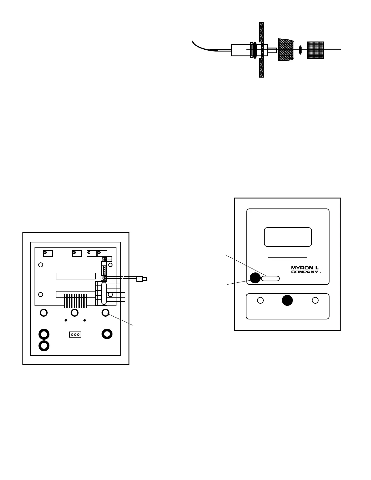
Display Select Switch installation
1. Using a small sharp knife or 1/4” (6.35mm) drill,
carefully cut open the hole on the right side of the front
panel, when viewed from the back, just below the Sensor
connectors on the Temperature module. See
gureIII.C.2.
2. Install push-button display switch into this hole and
tightenbezel.SeeguresIII.C.2&III.C.4.
3. Install push-button/cap on switch.
WARNING:
There are two (2) O-rings installed on the switch,
one (1) on the threaded shank and the other is under the push
button. Both of these must be re-installed to maintain IP64/
NEMA3ratings.SeegureIII.C.3.
4. Place “TEMPERATURE” label next to the switch. See
gureIII.C.4.
Electrical
1. Connect the display switch harness to the Temperature
ModuleasshowningureIII.C.1.
2. Connect the Temperature Sensor leads to the
TemperatureModuleaslabeledingureIII.C.1.
CAUTION: The sensor input connectors require only a small
screwdriver or a pen to push on the release levers. The release
levers may be broken or damaged if not pushed straight toward
the CB. DO NOT push the release levers sideways. Follow the
color code as labeled.
3. Connect0-5VDCoutput,ifdesired.
4. To test, turn power ON.
5. Press “TEMPERATURE” front panel switch, display will
show the temperature of the sensor.
6. Turn power OFF.
7. Continue or reinstall the front panel and tightly secure
both retaining screws, see REASSEMBLY below.
3. RECALIBRATION
Electronic Calibration Only. For System Calibration, see below.
The Temperature Module was calibrated at the factory, however,
if you wish to check the calibration the following procedure will
help you to accomplish this task. Exercise caution while per-
forming this procedure.
Requirements:
TP Calibration Module (TPC) or
Two .1% precision resistors -
ZERO-1000.0Ω(0°C=0.0V)
SPAN-1758.56Ω(200°C=5.0V)
One (1) jumper
ADVMsettoDCVolts,atweakerorsmallstandardslot
screwdriver.
SWITCH and O-RING ASSEMBLY
FRONT PANEL
TEMPERATURE
Label Location
750II
HIGHLOW
SET POINT
MICROSIEMENS / CM
TEMPERATURE
TEMPERATURE
Switch Location
FRONT PANEL
Rear View
Cut front label
out for Display
FSZERODISSP2 HYS2
DISPLAY CONNECTION
DISPLAY SWITCH
DISPLAY
TEMPERATURE
SENSOR INPUT
0-5VDC
OUTPUT
DISPLAY
TEMP
CONTROL
HARNESS
TEMP
SENSOR
(-)
(+)
BLU
+
0-5VD
INC
INC
DEC
DEC
BRN
BR BL OR - +
-
SPC
SELECT
TP/TPO - TEMPERATURE MODULE
 Loading...