24
FATAL TO PERSONNEL. ONLY QUALIFIED PERSON-
NEL SHOULD INSTALL ELECTRICAL EQUIPMENT.
Physical
If the front panel has all ready been removed from the enclosure
skip to #3.
1. Using a standard slot screwdriver remove the four (4)
screws on the front panel.
2. Carefully wiggle the front panel to loosen and pull gently
toward you. Do not pull more than about 8 inches/
20CM or you could damage the wiring harness.
3. Turn the front panel around so that the back side is
facing you.
4. Using a standard slot screwdriver remove the four (4)
screws holding the plastic display retainer plate to the
front panel. When the screws have been removed, the
plastic display retainer plate and the display will be free
from the front panel.
5. Set front panel down or carefully allow to hang from the
harness. Do not drop as the harness connector will pull
out allowing the front panel to fall.
6. While holding the display and the plastic display retainer
plate, carefully remove the display harness connector.
Do not drop the display. Remove and discard the plastic
display retainer plate.
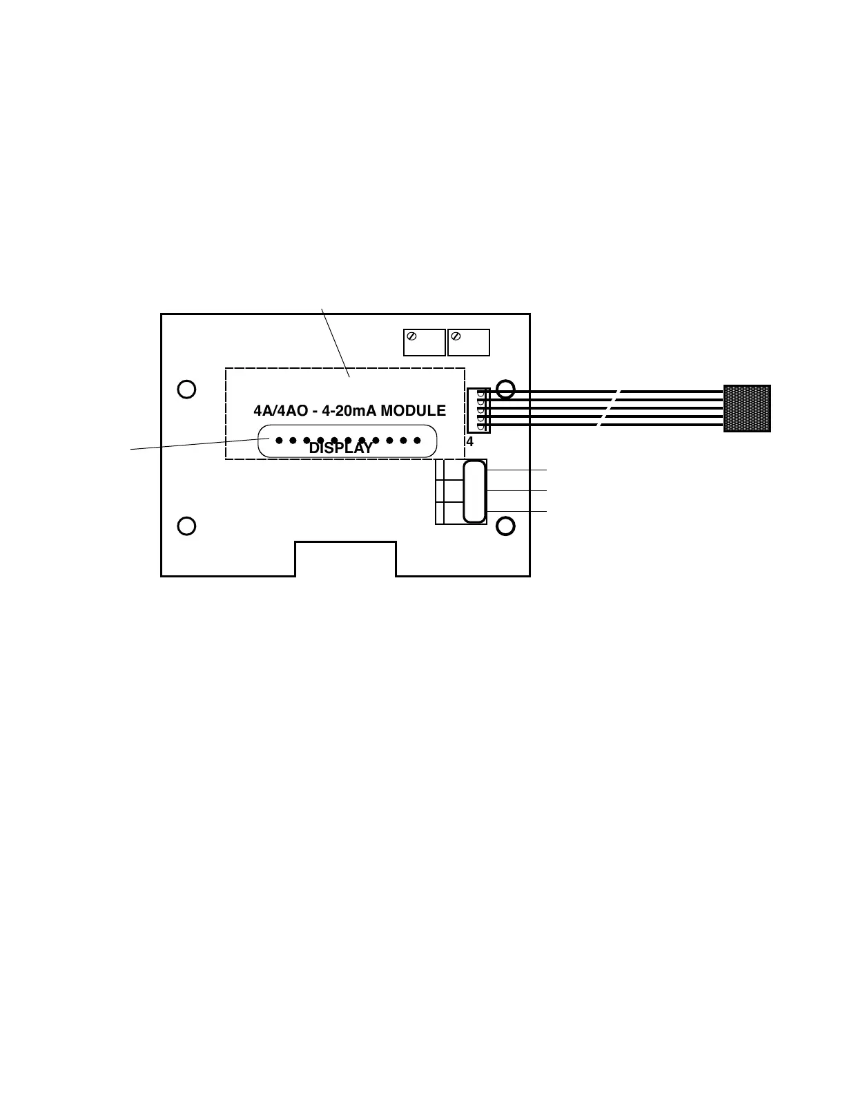
7. While still holding the display in the palm of your hand,
set the 4-20 Module over it with the display pins
protruding through the center opening as shown in
gureIII.B.3.
8. Reconnect the harness to the display as shown in
gureIII.B.3.
9. While holding the front panel, align the display to the
opening while at the same time align the 4-20 Module
mounting holes to the front panel.
10. Reinstall the four (4) screws and tighten.
Electrical
1. Connectthe4-20Module(ve)5wireharnesstothe
main circuit board at the location next to the display
harness marked “4-20”asshowningureIII.B.4.
2. Connect the signal and power wires as required, as
showninguresIII.B.1.&III.B.2.Thisassumesyou
have already connected the other end of the wires as
required.
a. Place the remote interface cable and user supplied
watertightcablerestraintintotheenclosure’s
appropriate access hole.
b. Neatly connect the signal cable wires to the
Monitor’sappropriateconnectorsasshownin
gureIII.B.3.
3. To test, turn power ON.
4. Press the Full Scale Test switch and monitor the output
atyourremotesite,orwithaDVMsettoDCmilliamps.
AttachtheDVMtotheoutputconnectorsperyour
requirements, i.e. self-powered or remote-powered, see
guresIII.B.1.&III.B.2.Ifthe4Amoduleisconnected
properly it will indicate 20mA.
5. Turn power OFF.
6. Carefullyreinstallthefrontpanel,bottomrst,ensureno
wires have been pinched between enclosure and front
panel.
7. Reinstall the four (4) screws and tighten.
8. To operate, turn power ON.
3. RECALIBRATION
The 4-20 Module was calibrated at the factory; however, if you
wish to check the calibration the following procedure will help
you to accomplish this task. Exercise caution while performing
this procedure.
Requirements; aDVMsettoDCmilliamps,atweakerorsmall
standard slot screwdriver.
This procedure assumes the front panel is removed.
For Resistivity models, please follow special notes (*)
1. If sensor is connected, disconnect sensor wires from
sensor terminal block. (* For Resistivity models,
connect the sensor wires (red, green, & neutral)
into the sensor terminal block. Use a jumper to
bridge the black and white terminals together.)
2. AttachtheDVMtotheoutputconnectorsperyour
requirements, i.e. self-powered or remote-powered,
seegureIII.B.5.
3. FORRESISTIVITYONLY:Addjumperbetween
Black(BK) and White(WT) connectors, see Figure III.B.4.
For Conductivity, go to step 4.
4. Turn power ON, with the front panel meter/display at
ZERO,theDVMshouldindicate4milliamps.
DISPLAY IS ON BACK SIDE OF 4-20 MODULE
RECONNECT
DISPLAY
CONNECTOR
HERE
SO PO PI
 Loading...