Module to the main Monitor/controller CB at the sensor
input location as shown on label.
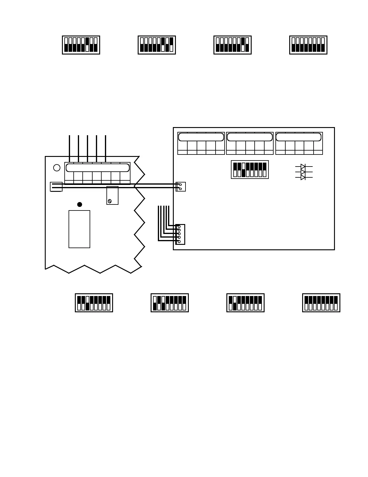
5. Attach the separate small cable harness from the 3 Sensor
Input Module to the small 2 pin male connector located
to the left of the sensor input connectors on the main
CB. NOT INSTALLED ON MONITOR ONLY MODELS.
Sensor Connections
For convenience, it is recommended you connect the Primary or
controllingsensortoSENSOR1position.Seegures1or6for
3SE.
CAUTION: The sensor input connectors require only a small
screwdriver or a pen to push on the release levers. Follow the
color code as marked. The release levers may be broken or
damaged if not pushed straight toward the CB. DO NOT push
the release levers sideways.
3. ALARM/CONTROL CONFIGURATION
Asshippedfromthefactory,the3SModuleisconguredsothat
only the Primary or First switch position SENSOR 1 is set to
alarm/controlasshowningure2,orgure7for3SE.Ifyour
particular application requirements are different, the following
willhelpyoutorecongurethealarm/controlfunctiontoanother
sensor or add a controlling sensor. Pick the appropriate scenario
below.
NOTE: the setpoints will not change nor are they separately
adjustable for each sensor.
3SO MODULE
If adding an alarm/control sensor.
1. Locate the 8 position select switch on the 3S Module.
2. Set appropriate select switch UP or ON, i.e. to add S3
sensor, set switch marked S3ON,seegureIII.F.3.
If changing alarm/control from one sensor to another, i.e. S1 to
S2 sensor.
1. Locate the 8 position select switch on the 3S Module.
2. Set the S1 select switch in the DOWN or OFF position.
3. Set the S2 select switch in the UP or ON position, see
41
COND
RES
X1
X10
X100
S1
S2
S3
COND
RES
X1
X10
X100
S1
S2
S3
COND
RES
X1
X10
X100
S1
S2
S3
COND
RES
X1
X10
X100
S1
S2
S3
3SR MODULE
3S
COND
RES
X1
X10
X100
S1
S2
S3
SENSOR
OUTPUT
SENSOR 1SENSOR 2SENSOR 3
ON
SELECT
SWITCH
COND
RES
X1
X10
X100
S1
S2
S3
BK WT RD GN NU R- R+
NOT INSTALLED ON MONITOR ONLY MODELS.
BK WT RD GN NUBK WT RD GN NU
SELECT
SWITCH
ON
3 SR MODULE
SENSOR
OUTPUT
3 SENSOR INPUT MODULE (3SE)
COND
RES
X1
X10
X100
S1
S2
S3
COND
RES
X1
X10
X100
S1
S2
S3
COND
RES
X1
X10
X100
S1
S2
S3
COND
RES
X1
X10
X100
S1
S2
S3
 Loading...