16
G. RE-RANGE YOUR MONITOR/CONTROLLER
(Range Module Installation)
1. DESCRIPTION
The 750 Series II Monitor/controllers have been designed for
easyeldre-rangeability.TheRangeModuleconsistsofa16
pin Header that plugs into a 16 pin socket.
For available ranges, see Range Selection Guide I.G. When
making large range changes, i.e. 5000 ppm to 50 ppt, a different
sensor may also be required as noted in the Range Selection
Guide.OrderRangeModulebyaddingtheprex“RM”tothe
range number as in examples below.
Conductivity/TDS Range Modules —
RMXXX i.e. = RM121 is a 0-2000µS
Resistivity Range Modules —
RMXX i.e.=RM11 isa0-20MΩ
NOTE: Some OEM models may not be re-ranged being
originallymanufacturedwithaxedrange.Ifyourapplication
requiresre-ranginganOEMmodel,rstcontactthesystem
manufacture for help. The Myron L
®
Company may re-range or
exchange your instrument at a cost.
2. INSTALLATION
Briey-
The new Range Module simply replaces the Range Module
presentlyinstalled,seegureII.G.1.
Multiplier label is added to analog models*.
Type label may be required if changing from Microsiemens to
Millisiemens or PPM/PPT.
The Full Scale reading is recalibrated.
IMPORTANT NOTES:
1. When changing ranges on Digital Monitor/ controllers
with the -45 option (4 1/2 digit backlit display), the following
modications may be required to the range module; RM123
thru 128 and RM16 require pin number 9 be removed or
bent toward the side, see Fig. II.G.2. On RM117 thru 122 a
jumper wire must be soldered to the RM, see Fig. II.G.3.
*2. Analog Monitor/controllers may require a scale change.
See section II.G.3 for the specic instructions.
WARNING: BEFORE STARTING, IF MONITOR/
CONTROLLER IS INSTALLED, ENSURE THE POWER IS
OFF. FAILURE TO DO SO COULD CAUSE DAMAGE TO
THE INSTRUMENT, AND COULD BE HARMFUL OR FATAL
TO PERSONNEL. ONLY QUALIFIED PERSONNEL SHOULD
INSTALL OR SERVICE ELECTRICAL EQUIPMENT.
Physical
NOTE: When opening instrument, remove front cover with care;
a ribbon cable connects the front panel and main board. If the
front panel has already been removed from the enclosure skip
to #4.
1. Using a standard slot screwdriver remove the four (4)
screws on the front panel.
2. Carefully wiggle the front panel to loosen and pull
gently toward you. Do not pull more than about
8 inches/20CM or you could damage the wiring
harness.
3. Turn the front panel around so that the back side is
facing you and set aside.
4. Locate and remove existing Range Module from MAIN
CircuitBoard,asshowningureII.G.1.Itisnoteasy
to remove, it was designed to stay in place under
adverse conditions.
5. With the pointer up, carefully align the new Range
Module to the socket on the MAIN Circuit Board as
showningureII.G.1.
6. Pressrmlyintoplace.
7. For analog models, add multiplier label to front panel.
SeeguresII.G.10andII.G.11forsuggestedlocations.
In some cases changing the meter scale will be
necessary. See Changing Analog Meter Scale, section
II.G.3.
8. Recalibrate, see CALIBRATION PROCEDURES,
sectionV.C.
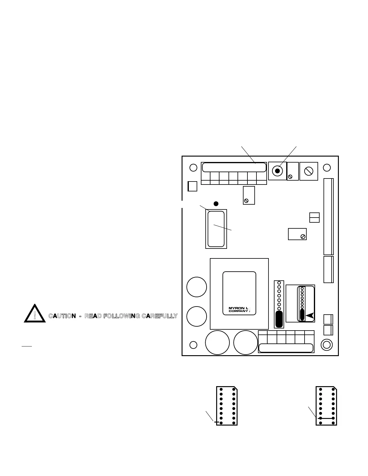
Main CB Assembly
Figure II.G.1
REMOVE
PIN #9
UP
DIGITAL 4 1/2 DIGIT LCD
MONITOR/CONTROLLERS ONLY
ADD JUMPER
CONNECTING
PINS 7 & 10
UP
RANGE MODULE
Bottom View
FIGURE II.G.2 FIGURE II.G.3
CAUTION - READ FOLLOWING CAREFULLY
BK WT RD GN NU R- R+
CHS
UP
}
HYS1SP1
FUSE*
115/
230
PWR C GD NC NO CM
DIS
CAL
3S
PA
RA
INC
DEC
SPC
TRANSFORMER
RANGE
MODULE
751 756
752 757
753 758
754 759
FS SW
FULL SCALE
PUSH TO TEST
0-10VDC
OUTPUT
-121
2000µS
POINTER
REMOVE TO INSTALL
SECOND RELAY

 Loading...