17
3. CHANGING ANALOG METER SCALE (DIAL)
After changing ranges on an analog model 750II it may be nec-
essary to change the meter scale (dial). The following steps will
guide you through the change. Please read caution carefully.
Exercise extreme caution while working on meter. Meter
movement, and/or pointer (needle) may be damaged beyond
repair. It is recommended only qualied personnel change
scales.
DO NOT allow dust to enter the case while it is open.
Failure to follow these instructions may cause irreparable
damage, and will VOID the warranty.
Briey-
The meter is removed from front panel (except OEM models).
The cover is removed.
The hex screws retaining the scale are removed, and scale
is slid out the top.
New scale is slid in place, and screws reinstalled.
Cover aligned, installed and zero set.
Physical
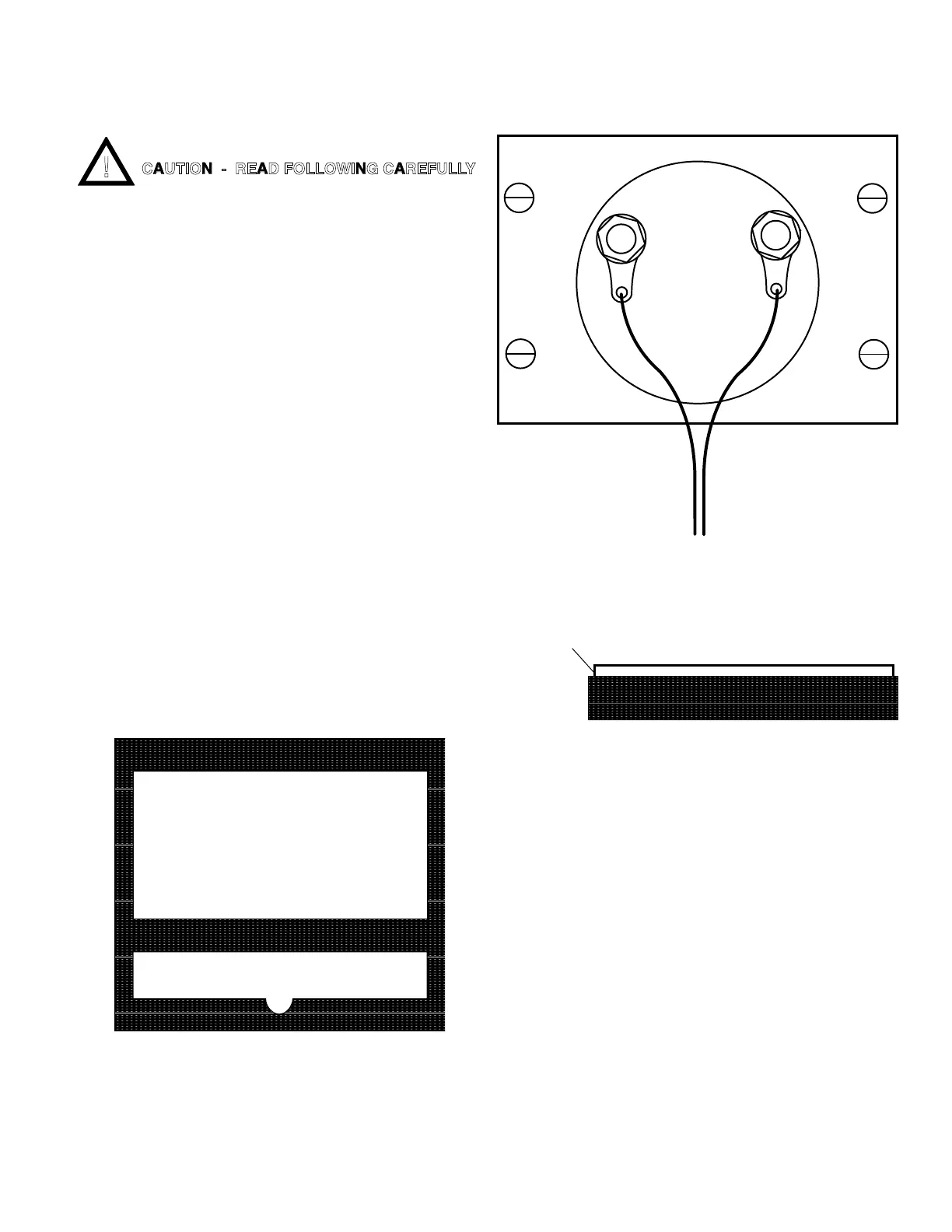
For OEM models skip to #4.
1. Using a wrench, nut driver or pliers remove the two
(2) large nuts retaining the circuit board wiring harness
connectors. Red wire is PLUS (+),
BrownwireisMINUS(-).SeegureII.G.4.
2. Using a standard slot screwdriver remove the four (4)
screws, and the backing plate holding the meter to the
frontpanelasshowningureII.G.4.
3. Remove meter. Do not lose the gasket between the
meter and the front panel it must be reinstalled upon
reassembly.SeegureII.G.5.Aligngaskettofront
panel so as the gasket does not show when meter is
assembled to front panel.
4. Using a wide blade standard slot screwdriver, starting
at a bottom corner, CAREFULLY pry the clear plastic
coverloosefromthemovementcase.SeegureII.G.6.
5. Using a 1/8” (3.2mm) hexdriver, remove the two (2)
smallscrewsholdingthescale(dial).SeegureII.G.7.
6. To remove the scale, lightly press on bottom of scale,
the top will lift up. Be extremely careful not to bend the
pointer (needle) or to move the Zero Adjust (ZA).
SeegureII.G.7.
7. Grasp top and slide scale slowly out from top. Be
extremely careful not to bend the pointer (needle) or to
movetheZeroAdjust(ZA).SeegureII.G.7.
8. Reverse the above procedure using the new scale.
NOTE: While replacing the clear plastic cover, ensure the
ZA screw pin on the cover aligns with the inverted “Y” shaped
slotonthemetermovement.SeegureII.G.7.
IF, the inverted “Y” shaped slot is inadvertently moved -
BEFORE installing cover:
a. Re-center the inverted “Y” to the meter case as
showningureII.G.7.
b. Center the Zero Adjust (ZA) PIN on the clear
plasticcoverasshowningureII.G.8.
9. Using a standard slot screwdriver, ensure the ZA is
operating - pointer swings left and right when turning
theZAwithastandardslotscrewdriver.Seegure
II.G.9.
10. SetMeterZEROasshowningureII.G.9.
11. Reinstall meter to front panel, reversing steps 1-3
(except OEM models).
GASKET
Harness to Main
CB Connector
Backing Plate
METER
Mounting Screws (4)
BROWN WIRERED WIRE
+
CLEAR COVER
Pry Here Carefully
Figure II.G.5
Figure II.G.4
Figure II.G.6
CAUTION - READ FOLLOWING CAREFULLY
 Loading...