53
B. OEM FRONT PANEL INDICATORS &
CONTROLS
The simulated OEM front panel illustrations to the right, and
switch and indicator operational descriptions have been pro-
vided to assist the OEM user in identifying and operating the
750 Series II Monitor/controllers.
RefertoSectionV.C.forSetupprocedures,andSectionV.D.for
Check-Out procedures.
1. RED “HIGH SET POINT” LED INDICATOR
TheredLEDindicatorlightisONonlywhenthewater’sconduc-
tivity/TDSreadingisHIGHorABOVEthesetpointadjustment
(LOW or BELOW on Resistivity). May be reversed if desired.
2. GREEN “LOW SET POINT” LED INDICATOR
ThegreenLEDindicatorlightisONonlywhenthewater’s
conductivity/TDS reading is LOW or BELOW the set point
adjustment(HIGHorABOVEonResistivity).Maybereversedif
desired.
3. “SET POINT” SWITCH(ES)
When the “SET POINT” switch is depressed, the internal set
point reading is immediately displayed on the front panel dis-
play.SeeguresIV.B.1thru4.
4. ANALOG METER OR DIGITAL DISPLAY
Panel mounted analog meter or digital display provide a continu-
ous readout of the water being monitored.
Conductivity/TDS Models 756II & 757II and Resistivity Models
751II & 752II are equipped with analog meter only as shown in
gureIV.B.4.
Conductivity/TDS Models 758II & 759II and Resistivity Models
753II & 754II are equipped with a 3 1/2 digit, 1/2” Liquid Crystal
DigitalDisplay,asshowninguresIV.B.1thru3&5.,witha4
1/2 digit backlit LCD as an option.
5. OPTIONAL PANEL MOUNTED ITEMS
TP/TPO Module Switch
A digital Monitor/controller with the optional TP/TPO Temperature
Module has an additional switch on the front panel as shown in
gureIV.B.1.Thispush-buttonmomentaryswitchwhenpushed
gives the user a direct reading of the temperature of the solution
from0-200°C.AdditionaloptionTH/THOincludesacontrol
functioncapability.SeegureIV.B.1.
Full Scale Test Switch (PTS/FST)
This optional feature allows the user to see the Full Scale TEST
value without opening the panel to push the internal switch. See
guresIV.B.1andIV.B.3fortypicalexamples.
Piezo Alarm
Audible alarm sounds off automatically when the set point is
reached. Mounted by OEM in any convenient location as shown
ingureIV.B.3.
WARNING: THE DISPLAY WILL BE IRREPARABLY
DAMAGED IF THE HARNESS IS INSTALLED UPSIDE-
DOWN. THE HARNESS MUST BE INSTALLED AS
SHOWN IN FIGURE II.E.6.
LOWSET POINT
TEMPERATURE
TEMPERATURE
FST
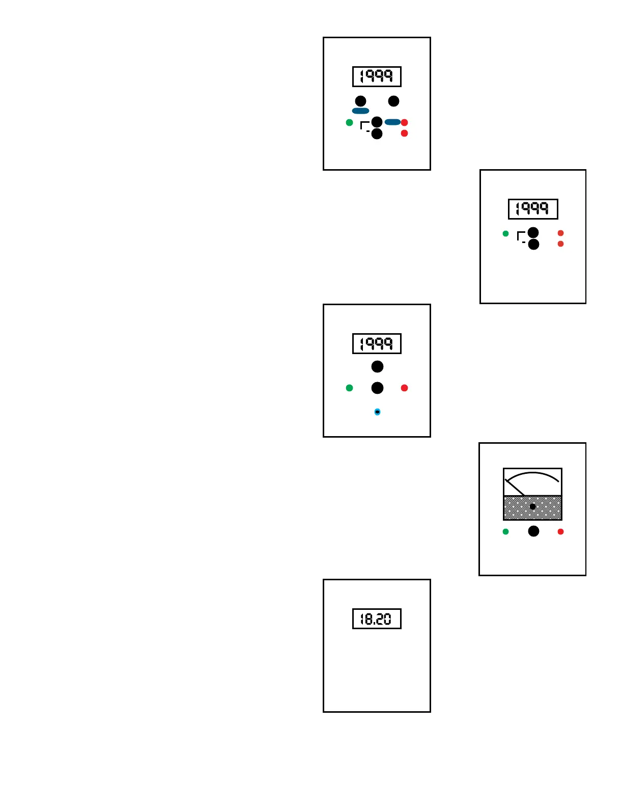
Figure IV.B.1
HIGH
LOWSET POINT
Figure IV.B.2
Digital Conductivity
Monitor/controller with
optional Dual
Alarm/controls
Digital Conductivity
Monitor/controller with
optional Dual
Alarm/controls, and
Temperature with
control function, and
Front Panel Test
Switch.
758II-121-SC-TP-THH-PTS
758II-121-SC
Figure IV.B.5
HIGHLOW
SET POINT
Figure IV.B.4
0 5
4
32
1
Figure IV.B.3
HIGHLOW
SET POINT
FST
NOTE: Boxes around displays to simulate OEM
panels.
Analog Conductivity
Monitor/controller
(Single Alarm/control)
Digital Conductivity
Monitor/controller with
optional Front Panel
Test Switch, Single
Alarm/control, and
Piezo Alarm.
Digital
Resistivity
Monitor
754II-11
757II-112
758II-121-PTS-PA

 Loading...