46
Sensor Connections
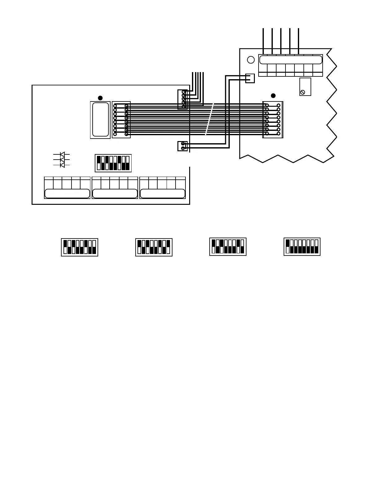
For convenience, it is recommended you connect the Primary or
controlling sensor to SENSOR 1 position as shown in
gureIII.H.1.
CAUTION: The sensor connectors require only a small screw-
driver or a pen to push on the release lever. Follow the color
code as marked. The release levers may be broken or damaged
if not pushed straight toward the CB. DO NOT push the release
levers sideways.
3. ALARM/CONTROL CONFIGURATION
Sensor Switch
Asshippedfromthefactory,the3SRModuleisconguredso
that only the Primary or First switch position “S1” is set to alarm/
control,gureIII.H.2.Ifyourparticularapplicationrequirements
aredifferent,thefollowingwillhelpyoutorecongurethealarm/
control function to another sensor or add a controlling sensor.
Pick the appropriate scenario below.
NOTE: the setpoints will not change nor are they separately
adjustable for each sensor.
If adding an alarm/control sensor.
1. Locate the 8 position select switch on the 3SR Module.
2. Set appropriate select switch UP or ON, i.e. to add S3
sensor, set switch marked S3 UP or ON, see
gureIII.H.3.
If changing alarm/control from one sensor to another, i.e. S1 to
S2 sensor.
1. Locate the 8 position select switch on the 3SR Module.
2. Set the S1 select switch in the DOWN or OFF position.
3. Set the S2 select switch in the UP or ON position, see
gureIII.H.4.
To disable the Sensor alarm/control function completely.
1. Locate the 8 position select switch on the 3SR Module.
2. Set all XprexedandSprexedselectswitchesinthe
DOWNorOFFposition,seegureIII.H.5.
Range Switch
Asshippedfromthefactory,the3SRModuleisconguredso
that only the Primary or First switch position X1 is set to alarm/
control,gureIII.H.6.Ifyourparticularapplicationrequirements
aredifferent,thefollowingwillhelpyoutorecongurethealarm/
control function to another range or add a controlling range. Pick
the appropriate scenario below. The setpoints will not change
nor are they separately adjustable for each range.
NOTE: The Range Switch is labeled:
SENSOR
SWITCH
BACK/CONNECTOR SIDE
-121
2000µS
UP
}
SENSOR
OUTPUT
TO SENSOR INPUT
3S
MAIN CIRCUIT BOARD
RANGE
SWITCH
Figure III.H.1
SENSOR 1SENSOR 2SENSOR 3
SENSOR 1
BK WT RD GN NU BK WT RD GN NU BK WT RD GN NU
BK WT RD GN NU R- R+
SENSOR 2 SENSOR 3
3S
ON
SELECT
SWITCH
Figure III.H.2
ON
Figure III.H.3
ON
Figure III.H.4 Figure III.H.5
ON ON
3 SENSOR/3 RANGE INPUT MODULE 3SR
NOT INSTALLED ON
MONITOR ONLY MODELS.
COND
RES
X1
X10
X100
S1
S2
S3
COND
RES
X1
X10
X100
S1
S2
S3
COND
RES
X1
X10
X100
S1
S2
S3
COND
RES
X1
X10
X100
S1
S2
S3
COND
RES
X1
X10
X100
S1
S2
S3

 Loading...