20
Front Panel
WARNING:
There are two (2) O-rings installed on the switches,
one (1) on the shank and the other is under the push button.
Both of these O-rings must be reinstalled to maintain IP65/
NEMA4Xratings.SeegureIII.A.3.
1-4 assumes this is a conversion from a single alarm/control.
Skip to #5 if new installation or assembly.
1. Carefully remove the RED LED from the front panel
by pulling lightly on the wires. It may be necessary to
useasmallatscrewdrivertoslightlyspreadthe
retaining ring.
2. Remove the set point switch from the front panel by
rotating the round bezel nut CCW on the front panel,
seegureIII.A.4.
3. Remove the LOWER front label.
4. Clean off remaining adhesive. Use alcohol, if possible.
5. Install DUAL alarm LOWER label, P# L2ALARM.
6. Install the SCO Second Alarm/Control RED LED in the
UPPERpositionasshowninguresIII.A.5&III.A.6.
7. Install the SCO Second Alarm/Control Set Point Switch
in the UPPER center position.
8. Re-install #1 (original) Set Point Switch in the LOWER
center position.
9. Re-install the #1 (original) RED LED in the LOWER
position.
10. The GREEN LED stays in the same location.
a. Set Point Conversion (SPC) /
Reversing Set Point
The alarm/control circuit(s) on all 750 Series II Conductivity/TDS
Monitor/controllersareconguredtotriggerthealarmrelayas
the Conductivity/TDS reading increases.
NOTE: On Resistivity Monitor/controllers the reverse is true, as
the reading decreases the alarm/control will trigger/sound.
Iftheuser’sapplicationrequiresit,thealarm/controlcircuit
maybeeasilyreconguredtotriggerthealarm/controlrelayas
the Conductivity (or ppm) reading decreases, or increases for
Resistivity.RefertogureIII.A.4forthelocationsoftheSPC
jumpers referred to in this section.
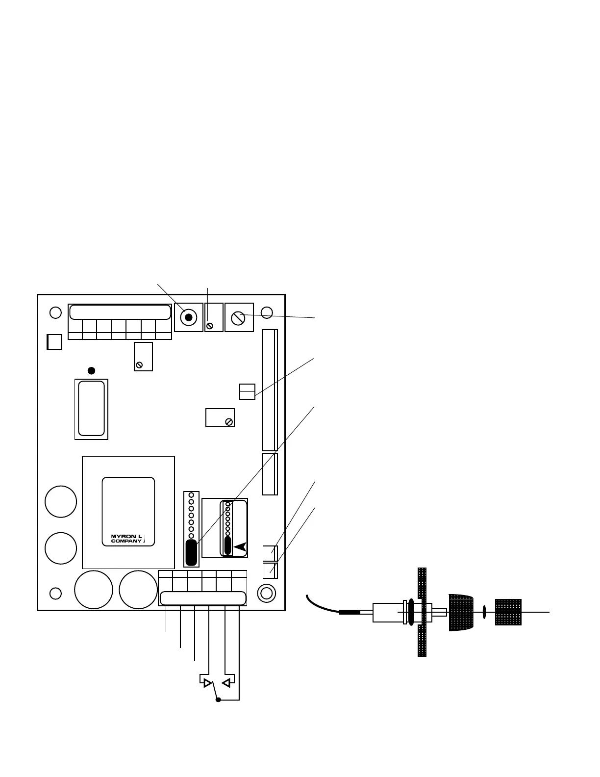
Figure III.A.2
SWITCH
BEZEL
NUT
PUSH
BUTTON
O-RING
O-RING
Switch / O-ring Assembly
Figure III.A.3
BK WT RD GN NU R- R+
RELAY #1
}
COM
{
POWER
AC LINE/DC+
AC NEUTRAL/DC-
GROUND
SET POINT #1
CONVERSION
CHS
GND
HYS1SP1FS SW
FUSE*
115/
230
NC NO
-121
2000µS
UP
}
DIS
CAL
3S
PA
RA
REMOVE JUMPER TO
INSTALL SC/SCO
SECOND ALARM/CONTROL
MODULE
SET POINT #1 HYSTERESIS
RIGHT INCREASING /
LEFT DECREASING
FULL SCALE
PUSH TO TEST
SET POINT #1 (low)
ADJUST
INC
DEC
SPC
751 756
752 757
753 758
754 759
SOLID STATE OUTPUT
(24VDC 30mA)
PIEZO ELECTRIC ALARM - PA™
OR
REMOTE ALARM - RA™ OR
CUSTOMER CONNECTION
PWR C GD NC NO CM
TRANSFORMER
REMOVE TO INSTALL
SECOND RELAY
 Loading...