c. Hysteresis (Dead Band) Adjustment*
Thehysteresisordeadbandisapproximately±3%oftheset
point at full scale as it leaves the factory. Under normal (most)
conditions it will not be necessary to adjust.
However, if you desire to make an adjustment please keep the
following in mind.
The adjustment is very simple and is based on set point loca-
tion. If the set point* is in the upper 75-100% of the scale, the
hysteresis control pot should be turned fully to the right.
If the set point is in the lower portion of the scale, i.e. 5-25% of
scale, the control pot may be turned fully to the left.
If you are operating in the center, 25-75% of scale, the control
pot may be adjusted in the center.
Or the hysteresis or dead band may be adjusted to tighten the
control of a particular process.
CAUTION: Adjusting the hysteresis too narrow may cause the
alarmtouctuate(on-off)duetoow,chemicalmixingorbub-
bles causing the relay to chatter. This condition is to be avoided,
it could damage your valves, pumps, etc. and will eventually
damage the relay.
* Applies to both set points.
The following is assuming the front panel is already removed and
the set points have been set, if not, see “Set Point Adjustment”.
1. Turn power ON.
2. Locate the Hysteresis Control (HYS1) located next to
the Set Point #1 (SP1) adjustment - it is a single turn
pot.SeegureIII.A.4.
3. Adjust as described in “Hysteresis (Dead Band)
Adjustment” or as desired.
4. Press set point test switch on the front panel to verify
Hysteresis is set as desired.
5. RepeatforSCOModule.SeegureIII.A.4.
6. Press set point test switch on the front panel to verify
Hysteresis is set as desired.
7. Turn power OFF.
d. Second Relay Connection
1. Place the user supplied relay interface cable and
watertightcablerestraintintotheenclosure’s
appropriate access hole.
2. Neatly connect wires to the relay connector as shown
ingureIII.A.4.
e. Solid State Output Options
24VDCUnregulated30mAmax.
Same as 4. above, SOLID STATE OUTPUT.
1. Piezo Electric Alarm - PA (option)
Plug PA connector to CB as shown (See
Figure III.A.4).
2. Remote Alarm - RA™ (option)
Plug RA connector to CB as shown (See
Figure III.A.4).
3. Connect to your own alarm or ?
Ensureyourrequirementsdonotexceedthe24VDC
Unregulated 30mA maximum.
Ensure the polarity is correct.
Attach your wires.
Attach harness connector to controller connector (RA)
pergureIII.A.4.
If necessary, you may order connector with 8” Harness
part #RAH, from the Myron L
®
Company.
REASSEMBLY:
1. Carefullyreinstallthefrontpanel,bottomrst.Ensure
no wires have been pinched between enclosure and
front panel.
2. Reinstall the four (4) screws and tighten.
3. To operate, turn power ON.
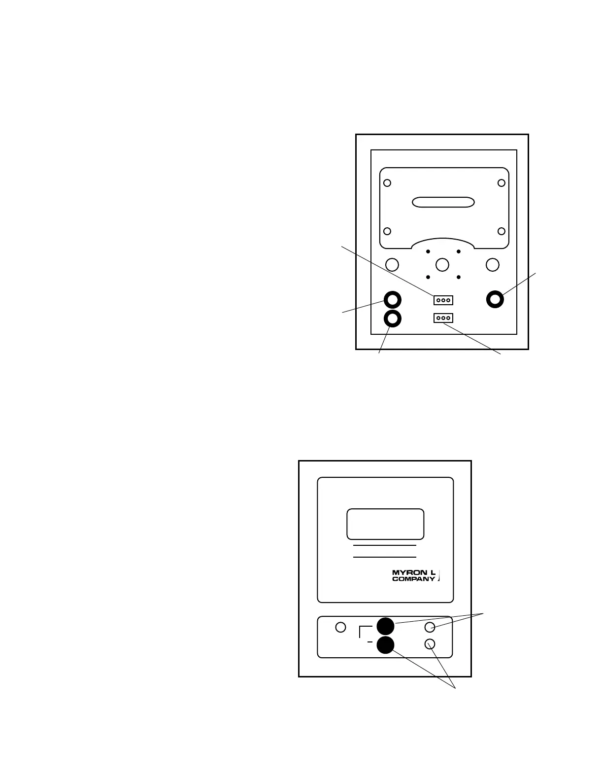
Figure 5
FRONT PANEL
Rear View
Primary/Main CB
Red LED
Switch
SC/SCO
Red LED
SC/SCO
Set Point
Switch
HIGH
LOWSET POINT
750II
MICROSIEMENS / CM
FRONT PANEL
Primary or Main CB
SC/SCO
Location
22

 Loading...